Quick Installation Guide TEW-740APBO
Table of Content 1 English 1. Before You Start 2. Hardware Configuration 3.
1. Before You Start Package Contents Ÿ TEW-740APBO Ÿ CD-ROM (User's Guide) Ÿ Quick Installation Guide Ÿ Proprietary PoE injector Ÿ Power adapter (12 V DC, 1 A) Ÿ Mounting Hardware Ÿ Grounding wire Minimum Requirements Ÿ Computer with a network port and web browser Ÿ A network switch or router with an available network LAN port Ÿ Additional TEW-740APBO H/W: v2.
РORTUGUÊS ESPAÑOL DEUTSCH FRANÇAIS ENGLISH 2. Hardware Setup and Configuration Note: Ÿ The default IP address of the TEW-740APBO is 192.168.10.100. To configure the TEW-740APBO, your network adapter must have an IP address within the 192.168.10.x subnet (e.g. 192.168.10.10). Please refer to the Appendix in the User's Guide for more information. Ÿ The initial configuration should be completed in a testing environment with two TEW-740APBO access points approximately 15 ft.
Phase 2: TEW-740APBO Unit #1 Hardware Setup and Configuration 1. Remove the cover of the access point by pulling and holding the tab in the vertical direction upward (based on the access point orientation below) and sliding the cover in the two locations noted below away from the access point. Pull and hold tab 2. Write down the MAC address (WiFi MAC) of the TEW-740APBO #1 access point.
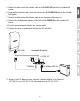
ENGLISH РORTUGUÊS ESPAÑOL DEUTSCH FRANÇAIS 3. Remove the tab on the far left by gently bending it back and forth until the tab is removed. This will create the opening for a RJ-45 network cable to be routed through. Tab 4. Using a network cable, connect one end of the cable to the LAN (PoE) port and push the cable into the cable guide on the far left, then through the opening that was created in the previous step.
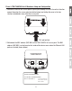
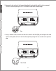
5. Connect the other end of the network cable to the P+DATA OUT port on the included PoE injector. 6. Using another network cable, connect one end to the 10/100 DATA IN port on the included PoE injector. 7. Connect the other end of the network cable to your computer's Ethernet port. 8. Connect the included power adapter to the PoE injector POWER IN on the included PoE injector. 9. Plug the connected power adapter into a power outlet. 10. Confirm the device is powered on through the LED indicators.
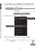
13. When prompted, login to the browser configuration page using the default user name and password settings. User Name: admin Password: admin Note: User Name and Password are case sensitive. ENGLISH РORTUGUÊS ESPAÑOL DEUTSCH FRANÇAIS 12. Open your web browser and type the IP address of the access point in the address bar, then press Enter. The default IP address is 192.168.10.100. 14. Click on the System tab and select Management.
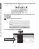
15. Under Administrator Password, change the default administrator password by typing in your new password in the fields provided and then click the Save button at the bottom of the page. Save Reboot 16. After the device saves changes and reboots, in the top menu, click on the System and click on Mode Setup.
ENGLISH 17. Click on the Mode field and click on WDS Mode. Then click Save & Reboot and when prompted to change settings, click Yes to reboot the device and apply the changes. Save & Reboot 18. In the top menu, click on System and click on VLAN Setup. System ESPAÑOL DEUTSCH FRANÇAIS WDS Mode РORTUGUÊS VLAN Setup 19. For the first entry in the VLAN List under the action column, click Network.
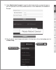
20. In the IP Setup section, enter the IP Address 192.168.10.50 and Netmask 255.255.255.0. Then click Save. In the menu located at the top, you will be prompted to reboot the device. Click the Reboot button and in the following page, click Reboot. When prompted to change settings, click Yes to reboot the device and apply the changes. Note: When configuring TEW-740APBO #2, enter the IP address settings 192.168.10.51 and Netmask 255.255.255.0. 21. Click on the Wireless tab and select Radio 0 Basic Setup.
ENGLISH 22. Click on the Wireless tab and select WDS Setup. ESPAÑOL DEUTSCH FRANÇAIS Wireless WDS Setup 23. Click Enabled for the WDS Setup and under Authentication, select AES. Enter a WDS PassPhrase (8-63 alphanumeric characters). РORTUGUÊS Note: When configuring TEW-740APBO Unit #2, the WDS AES Passphrase must be the same as TEW-740ABPO #1. 24. Under WDS Client Setup, check the first entry and enter the WiFi MAC address of TEW-740APBO #2. Then click Save.
25. When prompted, click Reboot at the top of the page, click the Reboot button, and click Yes to reboot and apply the configuration changes. Note: After the device reboots and applies changes, you will need to reconnect to device configuration page using the new IP address settings. Reboot Reboot Yes Phase 3: TEW-740APBO Unit #2 Hardware Setup and Configuration When configuring the TEW-740APBO #2, repeat all of the steps in Phase 2 setup and configuration. 1.
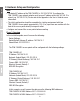
1. Leave your computer connected to TEW-740APBO #2 and keep the web management interface open. 2. Make sure both TEW-740APBO #1 and TEW-740APBO #2 access points are powered on approximately 15 ft. (5 m) apart from one another with front of access points directly facing each other. TEW-740APBO #1 TEW-740APBO #2 15 ft.
3. To verify connectivity, in the TEW-740ABPO #2 web management interface, click on Utility and click on Network Utility. Utility Network Utility 4. In the IP/Domain field, enter the IP address of TEW-740APBO #1, 192.168.10.50, then next to Times, click Ping. 5. Ping replies and 0% packet loss will indicate as successful point to point bridge connection between the TEW-740APBO #1 and #2. Note: If the connectivity test fails, wait for about a minute and try again.
1. Locate the grounding point located in the bottom section of the enclosure. Using a Phillps screwdriver, remove the grounding point screw (counter clockwise) and attach the included grounding wire to the grounding point screw. Reattach the ground screw (clockwise) along with the grounding wire. After installing the grounding wire, remove another tab on the enclosure by gently bending back and forth until the tab is removed. This will create the opening for the ground cable to be routed through.
2. Re-install the cover by lining up the guides into the notches as shown and push the cover down until the cover clips in and is secure. 3. Insert the included fasteners through the holes located at the back of the access point. 4. Wrap the fasteners around the pole where the access points will be installed. On the fasteners, insert the open end into the locking mechanism and pull tight until the access point is secured. 5.
ENGLISH РORTUGUÊS ESPAÑOL DEUTSCH FRANÇAIS Completed Installation Reference Internet Modem Router Building 1 Building 2 16
Manufacturer’s Name and Address TRENDnet, Inc. 20675 Manhattan Place Torrance, CA 90501 USA Zwolsestraat 156 2587 WB The Hague The Netherlands Product Information: TEW-740APBO / TEW-740APBO2K Model Number: 10 dBi Wireless N300 Outdoor PoE Access Point / Product Name: 10 dBi Wireless N300 Outdoor PoE Preconfigured Point-to-Point Bridge Kit TRENDnet Trade Name: TRENDnet hereby declare that the product is in compliance with the essential requirements and other relevant provisions under our sole responsibility.
Limited Warranty TRENDnet warrants its products against defects in material and workmanship, under normal use and service. Specific warranty periods are listed on each of the respective product pages on the TRENDnet website. Garantie Limitée TRENDnet garantit ses produits contre les problèmes de matériel ou de fabrication, dans des conditions normales d'utilisation et de service. Les périodes de garanties précises sont mentionnées sur chacun des pages produits du site web de TRENDnet.
Certifications This device complies with Part 15 of the FCC Rules. Operation is subject to the following two conditions: (1) This device may not cause harmful interference. (2) This device must accept any interference received. Including interference that may cause undesired operation. Waste electrical an electronic products must not be disposed of with household waste. Please recycle where facilities exist. Check with your Local Authority or Retailer for recycling advice.