Table of Contents CHAPTER1 1.1 1.2 About 3 Models Described in this Manual ...................................................................................5 Customer Support .........................................................................................................................5 CHAPTER2 2.1 2.2 2.2.1 2.3 2.4 2.4.1 2.4.2 2.5 BASIC INSTALLATION ............................................................................................9 Connecting the Hardware.........................
5.1 5.2 5.3 5.4 Configuring Host File.................................................................................................................38 Printing by LPD/LPR .................................................................................................................38 Using the Server on BSD UNIX/Linux........................................................................................38 Using the Server on RedHat Linux (Fedora Core)...................................................
CHAPTER14 UPGRADE FIRMWARE..........................................................................................86 CHAPTER15 THE INIT BUTTON .................................................................................................
Chapter1 Introduction Thank you for purchasing the TRENDnet TE100-MP1U/TE100-MP2U/TEW-MP2UW USB Multi-Function Print Server (in the following referred to as “Server”). This Server is designed to connect your All-In-One/Multifunction Peripheral, Printers, USB Mass Storages (Hard Drives, Flash Drives, and Memory Card Readers), and scanners, to your network, allowing all network users access to these shared USB devices resources. 1.
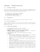
Chapter2 2.1 Product Overview Package Contents Verify that nothing is missing from the package by using the checking list below. Please contact your dealer if anything is missing or damaged. All packing materials are recyclable. Please confirm the items in the package below: 2.
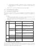
USB2 Indicator is lit while a USB device connects to USB2 Port of this Server. If it is not lit, or if it blinks, there is a problem with the USB device or this Server. Note: There is only one USB LED indicator for TE100-MP1U. 2.4 Installation Procedures 2.4.1 Installation and Integration Please refer to the table below to select the appropriate installation method. The Control Center Utility can be found in the CD-ROM or download from TRENDnet’s Website. # Note: 1.
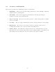
2.5 Features and Benefits This Server provides the following features and benefits: 1. Reliability: The Server provides high performance and reliability combined with low power consumption. 2. Flexibility: The Server supports print/File/Scan sharing in all major computer systems and environments. 3. Easy to Install: The Server installs, operates, and is managed in a reliable and easy fashion. 4. Security: You can assign administrator name and password to restrict login. 5.
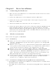
Chapter3 3.1 Basic Installation Connecting the Hardware 1. Make sure that your USB devices are switched off and that the Server’s Power Adapter is disconnected. 2. Connect the USB devices to the USB ports with the USB cables. 3. Connect the Server to the network with a twisted-pair category 5 cable, 10BaseT or 100BaseTX. 4. Turn on the USB devices and make sure it is ready for use. 5. Connect the Power Adapter to the Server.
# If the wireless parameters are not correct or not set yet, you have to use LAN to access MFP Server Control Center. 3. If the tool finds MFP Servers in your local area network, then you have to select a MFP Server from the server list. 4. Double click the highlighted server (or click the “Configure MFP Server” button) and type the server’s administrator (default: admin) and password (default: admin). 5. After you login successfully, from the Server menu, select wireless.
8. If the wireless network is secured by WPA-PSK/TKIP, the shared key must be set correctly.
9. Click Apply to save your settings. And the server will reboot. 10. You have now finished the procedure of setting the wireless parameters. # In infrastructure mode, TEW-MP2U searches all channels to join the matched wireless service set. In ad-hoc mode, TEW-MP2U searches all channels to join the matched wireless ad-hoc service set too, however, if none are found, TEW-MP2U creates that service set in the assigned channel. # 3.2.3 In ad-hoc mode, WPA-PSK/TKIP is not allowed.
# If the wireless parameters are not correct or not set yet, you have to use LAN to access Web Pages. # If the TCP/IP parameters of TEW-MP2U are not correct, you have to use MFP Server Control Center to set the TCP/IP parameters first. 2. Go to the web page and click CONFIG icon. 3. Login your administrator (default: admin) and password (default: admin). 4. Click Wireless icon.
5. In order to join an existing wireless network, you have to set the correct network type (infrastructure or ad-hoc), SSID, and the correct security method with the correct key information. 6. If the wireless network is secured by WEP64 or WEP128, key index and WEP key must be set correctly.
7. If the wireless network is secured by WPA-PSK/TKIP, the shared key must be set correctly.
8. Click Submit to save your settings. And the server will reboot. 9. You have now finished the procedure of setting the wireless parameters. # In infrastructure mode, TEW-MP2U searches all channels to join the matched wireless service set. In ad-hoc mode, TEW-MP2U searches all channels to join the matched wireless ad-hoc service set too, however, if none are found, TEW-MP2U creates that service set in the assigned channel. # In ad-hoc mode, WPA-PSK/TKIP is not allowed.
3.3.5 Server Names and Server Name Rules The default server name of the Server is “TE100-MP1U” or “TE100-MP2U” or “TEW-MP2U”. If you put two or more Servers in your local area network, to avoid using the same server names you have to change the server names by using the Control Center or the Server’s web pages. If your server name is longer than 15 characters, the Server uses only the first 15 characters. 3.3.
14. Double click the highlight list and enter the Server’s administrator (default: admin) and password (default: admin). 15. After you have logged in successfully, select TCP/IP from the Server’s menu. The Set IP Address dialog appears.
16. Click the button corresponding to your choice of IP setting method (static or dynamic using DHCP). When assigning a static IP address you also have to define Subnet Mask and Default Gateway. If you choose Automatically get IP by DHCP, you can use desired DNS by clicking the Manual DNS button and manually assigning a DNS. 17. Click Apply to save your settings. And the Server will reboot. 18. You have now finished the procedure of setting the IP address. 3.3.
4. Enter administrator (default: admin) and password (default: admin). 5. Click TCP/IP icon. 6.
dynamic using DHCP). When assigning a static IP address you also have to define Subnet Mask and Default Gateway. 7. Click Submit to save your settings. And the Server will reboot. You have now finished the procedure of setting the IP address. 3.4 Name of USB Device 3.4.1 Printer Names 1. The system will set the printer model names as the default printer names. The system only allows a 12-character long USB device name.
Chapter4 4.1 Print Server in Windows Overview of Installation Methods This chapter describes how to add network printers.
4.2.1 The Server and Windows PC on Same LAN 4.2.2 The Server and Windows PC on Different LANs Example: Wired Windows PC across Internet 4.3 Setting up Local Windows Printer Driver You are advised to install your Windows printer driver in advance. For most printers, you can install the printer drivers with the following procedure: 1. Click Start, click Control Panel, click Printers and Other Hardware, and then click Printers and Faxes. 2.
5. Choose whether you want to share the printer with other network users. Do you want to print a test page? Select the appropriate radio button and click Next and Finish. 4.4 Adding Network Printers in Windows Follow the instructions below to use the standard Windows Add Printer Wizard and the Control Center for adding a network printer in Windows 98 SE, ME, 2000, XP and 2003. # Note: 1. Before adding a network printer, you are advised to install the local Windows printer driver in advance. 2.
5. In the Printer Name or IP Address box, enter the Server Name of the Server or IP address of the Server. In the Port Name box, enter your desired names or USB1_LPR or USB2_LPR for printer connected to USB1 port and USB2 port, respectively.
Address box. 6. Click Next. 7. Click Custom/settings. 8. Click Settings and confirm that the settings are as below. The queue names are USB1_LQ, USB2_LQ for USB1 port 1 and USB2 port, respectively. Click OK.
9.
4.4.2 Using the Control Center for LPR Printing Windows Platform: Windows 2000, XP and 2003 1. Start the Control Center, right-click on your Server and select Set Printer. 2. Select USB1 Port or USB2 Port to add the printer in Set printer in box, choose to use Server Name or IP address to represent the Server in Select IP address or Host Name in printer port box, and select the network printing protocol of Printing with LPR (Line Printer Remote).
# If your Server is running on a different LAN than your Windows PC such as Internet PC, you must choose IP address in Select IP address or Host Name in printer port box. 3. Click Apply. 4. Select the desired printer driver and click Set Port to Printer. 5. If you cannot find any printer driver in Printer List, please install your printer driver first or click Add New Printer to install the printer driver. 4.4.
Number values are 9100, 9101 for USB port 1 and USB port 2, respectively. Refer to the Server’s web pages or the Control Center, you can get exact values. Click OK. 9. Click Finish.
4.4.4 Using the Control Center for Raw TCP/JetDirect Printing Windows Platform: Windows 2000, XP and 2003 1. Start the Control Center, right-click on your Server and select Set Printer. 2. Select USB1 Port or USB2 Port to add the printer in Set printer in box, choose to use or IP address to represent the Server in Select IP Address or Host Name in printer port box, and select the network printing protocol of Print with Raw TCP Mode.
# If your Server is running on a different LAN than your Windows PC such as Internet PC, you must choose IP address in Select IP Address or Host Name in printer port box. 3. Click Apply. 4. Select the desired printer driver and click Set Port to Printer.
5. If you cannot find any printer driver in Printer List, please install your printer driver first or click Add New Printer to install the printer driver. 4.4.5 # # Using Standard Windows Methods for SMB/CIFS Printing Before using SMB/CIFS printing, you have to login the SMB/CIF Print/File server in advance and then you may use it; otherwise you have to disable SMB/CIFS Print/File Server Authentication.
# If your Server is running on a different LAN than your windows PC such as Internet PC, you must enter IP address in Port Name box. 6. Click OK, and then select a Windows driver for your printer. If you already have the printer’s driver installed, you will be asked whether to keep it or to replace it. Click Next. 7. Choose whether you want to share the printer with other network users. Do you want to print a test page? Select the appropriate radio button and click Next and Finish. 4.4.
# If your Server is running on a different LAN than your Windows PC such as Internet PC, you must choose IP address in Select IP address or Host Name in printer port box. 3. Click Apply. 4. Select the desired printer driver and click Set Port to Printer.
5. If you cannot find any printer driver in Printer List, please install your printer driver first or click Add New Printer to install the printer driver. 4.4.7 Using Standard Windows Method for IPP Printing Windows Platform: Windows 98 SE, ME, 2000, XP and 2003 1. Click Start, click Control Panel, click Printers and Other Hardware, and then click Printers and Faxes. 2. Double click Add Printer to start the Add Printer Wizard, and then click Next. 3.
5. Click Next and then continue Windows Add Printer Wizard.
Chapter5 Print Server in Unix/Linux This chapter describes how to add network printers to Unix/Linux PC. 5.1 Configuring Host File If using IP administration system like DNS, manually registering the Server Name and IP address may be not required. Otherwise, you have to edit hosts file and contact your network administrator. 1. Log in to Linux machine by “root”. # login root 2. Register the Server’s Server Name and IP address into /etc/hosts file. To edit host file, use an editor, e.g. “vi”.
:sd=/var/spool/lpd/Printer1:\ ---(C) :lf=/var/spool/lpd/Printer1/Printer1_errs: ---(D) where (A) Describes the printer name. (B) lp: Device file name to connect printer. No name designation required on the network. rm: Server Name for the remote printer. Enter the Server Name registered to /etc/hosts file. rp: Remote printer name. Please input the remote printer queue name. (C) sd: Spool directory name. It must be the absolute path. (D) lf: Error log file name. It must be the absolute path. 3.
2. Click on the New button in the Printer configuration window. 3. Click on the Forward button in the Add a new print queue window.
4. Fill in your desired printer name and description (optional) in Queue name window and then click on the Forward button. 5. In Queue type window, you will now be asked to specify which Printer Queue type you are using, select the one option form Networked Unix (LPD), Networked CUPS (IPP), Networked Windows (SMB) and Networked JetDirect options. Click on the Forward button. 6. Fill in parameters for Queue type window: A.
192.168.1.100 and it connects to HP PSC 1300 MFP via USB1 port. You can enter IP address in the Server box as 192.168.1.100 and Queue name in Queue box as USB1_LQ. B. Networked JetDirect: Fill in the Server’s IP address and protocol’s TCP port and then click the Forward button. Example: If your Server’s IP address is 192.168.1.100 and it connects HP PSC 1300 MFP via USB1 port. You can enter IP address in the Server box as 192.168.1.100 and TCP Port in Port box as 9100.
C. Networked Windows (SMB): i. Click on the Specify button to specify SMB server Authentication. ii. Fill in the Workgroup, Server Name, User name and Password in Authentication window and then click on the OK button. iii. Click on the Forward button.
D. Networked CUPS (IPP): Fill in the Server’s IP address and printer name then click the Forward button. Example: If your Server’s IP address is 192.168.1.100 and its printer name is psc 1300 ser. You can enter IP address in Server box as 192.168.1.100 and printer name in Path box as psc 1300 ser. 7. Select your printer driver. Click on the Forward button. Windows will display the Finish, and create the new print queue folder.
8. Click Finish button.
Chapter6 File Server This chapter describes the file server function of the Server which allows USB storage devices to be shared across a network by using SMB: NetBIOS over TCP/IP and FTP protocol. 6.1 Preliminary 1. This product supports a file format of FAT12/16/32 and NTFS. However, the “write” operation on NTFS is only supported in NetUSB mode. Please refer to the Storage Access Mode. 2.
6.4 Supported Codepages - What is codepage? Used by the system to encode and interpret string characters. Codepage formats are not the same for each language. Some languages, such as Japanese have multibyte characters, while others, such as English and German, need only one byte to represent each character. - Filename Encoding of FAT File System This is known as an 8.3 file name, a short file name using codepage encoding. The FAT file system also supports file names that can be up to 255 characters long.
5. Select your codepage form File Server Codepage box and click Apply. B. Using Server’s Web Pages 1. Go to the web page, click CONFIG 2. Login your administrator (default: admin) and password (default: admin). 3. After you have logged in successfully, setting General Configuration dialog appears.
4. Select your codepage form File Server Codepage box and click Apply. 6.5 Adding Your USB Mass Storages to Network with Security You can use the following protocols to share your USB Mass Storages with user level security in network: SMB/CIFS: NetBIOS over TCP/IP FTP The protocols are shown in Supported Protocols box of the Control Center or the Server’s web pages. 6.5.1 Setting up File Server Using the Control Center 1. Start the Control Center and Auto-searching Server window will appear. 2.
5. Set up File Server Configuration: Set SMB/CIFS Print/File Server A. Enable SMB/CIFS Print/File Server: select the item, if you want to support SMB/CIFS print/File server. Enable Internet Access: clear the item, if you do not allow that users can access your SMB/CIFS server via Internet. If you select the item, you allow Internet users can access your storage using the SMB/CIFS protocol.
C. 6.5.2 number. Enable Passive Mode: select the item, if you want to allow that your FTP server can accept passive mode command. Enable Server Authentication: select the item, if you want to share your storage with user level security which requires user name and password to login. If you clear the item, your storage will be shared without security.
4. Set up File Server Configuration: A. Set SMB/CIFS Print/File Server Enable SMB/CIFS Print/File Server: select the item, if you want to support SMB/CIFS print/File server. Enable Internet Access: clear the item, if you do not allow that users can access your SMB/CIFS server via Internet. If you select the item, you allow Internet users can access your storage using the SMB/CIFS protocol.
3. Click Display the Computers of Workgroup 4. Double click Microsoft Windows Network icon. 5. Double click the Workgroup that the Server belongs to. The default Workgroup name is “WORKGROUP”. You can refer to Control Center or the Server’s web pages to get it. You will see that the Server is displayed as its server name. 6.
1. Open Microsoft IE 2. In Web Address List, enter command: “ftp://Server’s Server Name“ or “ftp://Server’s IP address”. If you have changed the default FTP port : 21 to the new value, you have to add the new port number in the tail of command as “ftp://Server’s Server Name: ftp port” or “ftp://Server’s IP address: ftp port”. 3.
Chapter7 7.1 The NetUSB Technology Introduction The goal of TE100-MP1U/TE100-MP2U/TEW-MP2U USB MFP Server is to provide the print/scan/file server in a single product. For printers and scanners, there is no industrial standard. In order to support many different models of printers and scanners from various vendors, one way is putting so many printer/scanner drivers into a single product. Obviously this is very hard and not practical.
operation is a software operation that simulates the disconnection of the USB device. Once the connect operation is successful, the operations to use that USB device are just the same as if the USB device is directly connected to the PC. If a USB device is “connected” by a PC, we say that PC has the ownership of the USB device. Only one PC can get the ownership of a USB device at the same time.
D. Click the server. Then all USB devices attached on the server will be shown. E. Please follow the user manual of the USB device to do the driver installation. For example, you may put the driver CD of the USB device in the CDROM to install the driver. When you are asked to plug in the USB device into PC’s USB port, either before running the driver setup program or during the execution of the driver setup program (This depends on the USB device. Please check the user manual from the vendor.
G. PC will automatically detect the plug-in of the USB device. On the right side of Windows Task Bar, you can see the information of the new device. Continue to follow the user manual of the USB device to do the rest jobs of installation, until the driver installation finished. After the installation, you can see the newly created devices on the PC. If the USB device is a MFP, you can see a new printer and a new scanner from the “Control Panel”. 7.3.
D. Choose the desired printer. The desired printer must be the Windows printer (this is a logical printer) that matches the printer attached on the MFP Server (this is a physical printer). Then click the “Apply” button. E. Then, the printer will be marked as an “Auto-Connected Printer” in red. If you choose “Auto-Connected Printer List” in the “Tools” menu, you can see a newly created item that describes the association between the Windows printer and the physical printer on the server.
F. Then try to issue a print job to the desired printer. You will see the Control Center will automatically do a connect operation. Then, the print job will be issued to that printer. This is so-called “Auto Connect Print” operation. G. Of course you can issue print jobs using manual “connect” and “disconnect” rather than “Auto Connect Print”. To do this, click on the printer, then click the “Connect” button.
E. Then the “Scanner Wizard” will run. Set the options as your need. Then submit the scan job. F. After the scanning finished, click the “Disconnect” button in the Control Center to release the ownership of the scanner (or MFP).
before and after the scanning, respectively. We will introduce “auto-connect scanning” in the following section. 7.3.4 NetUSB Scanning using Network Scan For NetUSB scanning, we recommend you use Network Scan as the following steps. A. In the Control Center, click the MFP Server that has the desired MFP attached. B. Click the desired MFP. C. Click the “Network Scanner” button. Then you can see that the Control Center will automatically do a “connect” operation. The following window will appear. D.
E. F. Follow the usual steps to do scanning. After the scanning, close the “Auto-Connect Scanner” window. 7.3.5 Accessing USB Storage using NetUSB Technology Before you use NetUSB technology to access USB storage, please make sure the storage access mode is in NetUSB mode. A. In the Control Center, click the MFP Server that has the desired USB storage device attached. B. Click the desired USB storage device.
C. Click the “Connect” button to manually connect the USB storage device. D. Now your PC will have a new disk. For example, if you connect a flash drive, your PC will have a new “removable disk”. You can see the storage icon in the system tray, as the following figure. E. F. Just use the new disk as a general disk. After you finish the disk operations, click the storage icon in the system tray and choose “Safely remove USB Mass Storage Device”. G.
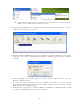
Chapter8 The Control Center This chapter describes how to use the Control Center. 8.1 Installing Control Center 1. Insert the included CD into the personal computer. The Autorun screen as in the following should appear. 2. Click Install Utility button. 3. Click Next, if you see any Next button in installation windows. 4. Click Finish. 8.2 Using the Control Center 8.2.
Note 1: You can also right-click the mouse button on the highlighted MFP Server to get the “Configure Server”, “Goto Homepage”, “Set Printer”, and “Network Storage” functions. Note2: You can also double-click on the highlighted server to get the “Configure Server” function. 8.2.2 Displaying Server Status You can start the Control Center and click on a server to see its status which includes Server Information, TCP/IP status, and Supported Protocols. 8.2.
5 Enable SMB/CIFS Print/File Server: select or clear Enable SMB/CIFS Print/File Server support. It is enabled in Factory Default. - Enable Internet Access: select or clear Enable Internet Access support. If you clear the item, you do not allow that users can access your SMB/CIFS server via Internet. If you select the item, you allow Internet users can access your storage using the SMB/CIFS protocol. - Enable Server Authentication: select or clear Enable Server Authentication support.
Storage Access Mode 1. Server Mode: In this mode, you can access the USB storage via FTP or SMB/CIFS protocols. FAT16/32 file format is fully supported in this mode. For NTFS, however, only the “read” operation is supported. This is the default mode. 2. NetUSB Mode: In this mode, you can access the USB storage using NetUSB technology. FAT16/32 and NTFS file formats are supported, but only one user is allowed to access the storage at the same time.
5 Retype Password: confirm your previous password typing. User Accounts list 5 User name: add a new user account for accessing the storage attached to the Server. 5 Password: set a password for added user. 5 Permission: select Read-Only or Read-Write permission to access File servers. 5 Add: click Add button, after entering the user name, corresponding password, and Permission selection. The account will take effect once shown in the blank below. 5 Delete: delete the existing user account.
5 SysLocation: enter some letters for variable of SysLocation that represents the location of system. 5 EnableAuthenTrap: enter 1 or 2 for the variable of EnableAuthenTrap that represents to enable (1) or disable (2) to send Trap packets receiving the wrong Community name. SNMP V3 5 Enable SNMP V3: select or clear Enable SnmpV3 support 5 User Security name: set user security name of SNMP v3 5 Auth Password: set authentication password of SNMP v3. 5 Privacy Password: set privacy password of SNMP v3.
5 5 5 5 Cc: stands for carbon copy; enter an e-mail address to send that mail to a second person. SMTP Server requires authentication: login to remote SMTP server which requires authentication. Account Name: enter account name for remote SMTP server. Password: enter account’s password for remote SMTP server.
8.3 Quitting the Control Center The Control Center doesn’t really quit if you click the “X” box (close box) at the top right corner of the window. Instead, it just minimizes itself to the system tray. There are two ways to really close the Control Center. The first way is choosing “Exit” item in the “File” menu in the Control Center. The second way is right-clicking the icon of the Control Center in the system tray and choosing the “Exit” item.
Chapter9 9.1 The Server’s Web Pages Introduction The Server runs the daemon of http server, httpd on TCP port: 80. Users may use the web pages to see the Server’s system status and configure the Server. 9.2 Using the Server’s Web Pages 9.2.1 Displaying Server Status You can see the status of Host Information, TCP/IP, Support Protocol and USB devices.
9.2.2 Setting up Server Configuration To set up the Server configuration, the system will request user to enter administrator (default: admin) and password (default: admin) to login. General Configuration Server Information: You have to set some information for networking using SMB protocol: 5 Server Name: the name to represent the Server for using SMB protocol 5 Workgroup: the name of the SMB workgroup that the Server belongs to.
storage or printer with user level security which requires user name and password to login. If you clear the item, your storage will be shared without security. 5 Enable FTP Server: select or clear Enable FTP Server support. It is enabled in Factory Default and users may set some parameters as follows: - FTP Port: enter an integer number to set FTP server’s TCP port (default: 21) - Set Maximum Session Number: select or clear Set Maximum Session Number support.
Storage Access Mode 1. Server Mode: In this mode, you can access the USB storage via FTP or SMB/CIFS protocols. Only FAT16/32 file format is supported in this mode. This is the default mode. 2. NetUSB Mode: In this mode, you can access the USB storage using NetUSB technology. In this mode, FAT16/32 and NTFS file formats are supported, but only one user is allowed to access the storage at the same time. Please refer to chapter 9 for the details about NetUSB technology.
5 5 5 5 Password: set a password for added user. Permission: select Read-Only or Read-Write permission to access File servers. Add: click Add button, after entering the user name, corresponding password, and Permission selection. The account will take effect once shown in the blank below. Delete: delete the existing user account. SNMP: You can set community and some parameters for SNMP server. Furthermore, you can enable SNMP v3 for more security.
receiving the wrong Community name. SNMP V3 5 Enable SNMP V3: select or clear Enable SnmpV3 support 5 User Security name: set user security name of SNMP v3 5 Auth Password: set authentication password of SNMP v3. 5 Privacy Password: set privacy password of SNMP v3. Restart Server: click this button, the Server will restart.
Maintenance If you want to restore factory default values of the Server and upgrade new firmware, you can use the Maintenance tool. 5 Factory Default: click this button, the Server will restore factory default values. 5 Download New Firmware from Website: click this button to download new firmware or user software from this product’s public website. 5 Upgrade Firmware: click Open to find the firmware file to be upgraded. Click Upgrade to upload the firmware into the Server.
Chapter10 Email Alerting This Server emails a notification to the user at these events: 1. Adding or Removing a USB device. 2. System Error. Chapter11 SNMP This Server runs an SNMP daemon supporting SNMP v1, v2c, and v3 protocols (Simple Network Management Protocol). Users can use SNMP client software such as HP OpenView to manage the Server. The Server supports all relevant parts of MIB-II and a private MIB. You can set these MIB variables from the Server’s web pages or by using the Control Center.
Chapter12 Troubleshooting This chapter provides useful information to help you resolve difficulties that you may experience with your Server. Fault symptoms, possible causes, and remedial actions are provided within a quick reference table. This Server’s USB ports only support MFPs, printers, scanners, and mass storage. 12.
Chapter13 Restore Factory Defaults You may restore the Server’s default parameters by one of the following methods. 13.1 Using the Control Center 1. Start the Control Center. 2. If the tool finds Servers in your local area network, then you have to select a Server from the Server List. 3. Double click the highlight list and enter the Server’s administrator (default: admin) and password (default: admin). 4. After you have logged in successfully, from the Server menu, select Maintenance.
z Code Page of File Server: Western European TCP/IP z Automatically get IP by DHCP: Enabled - Manual DNS: None (Disabled). z Static IP: Disabled - IP Address: 192.168.1.100 - Subnet Mask: 255.255.255.
Email z SMTP Protocol: Disabled z SMTP Server Name: None z SMTP Port Number: 25 z Subject: None z From Address: None z To Address: None z Cc: None z SMTP Server requires authentication: Disabled - Account Name: None - Password: None 85
Chapter14 Upgrade Firmware This chapter describes how to upgrade firmware. Please follow one of the following Procedures: Procedure A: Using the Control Center 1. Open Control Center. It will automatically search the existing Servers and display their statuses. 2. Select the Server that you want to upgrade the firmware. Double click the selected Server and enter Administrator (default: admin) and Password (default: admin). 3. Select the Maintenance button. 4.
3. First, run Control Center. It will automatically search for Servers on the LAN. Then Servers’ IP addresses will be shown in Control Center. 4. Run any Web browser, like Microsoft Internet Explorer. Go to “http://Server’s IP address “or “http://Server’s Server Name” to access the Server's home page. 5. Click CONFIG at the top of the menu. 6. Login the Server with Administrator (default: admin) and Password (default: admin). 7. Click Maintenance. 8. Click Upgrade Firmware. 9.
1. Plug in the power adaptor while pressing the Init button until LED indicators of Power, USB1 and USB2 blink. (For TRENDnet 301, only USB1 LED will blink.) Please note that after that, the Server will operate using the factory default values after restarting, i.e., your Server’s configuration will recover to Factory Default values. 2. Start the TFTP client Tool: Image Burner 3. Click Open Image to open your new firmware.
Chapter15 The Init Button The Init button is used for maintenance: Simultaneously press Init button and turn on (by plugging in the power adaptor) the Server until USB1 and USB2 LED indicators simultaneously blink. (For TE100-MP1U, only USB1 LED indicator will blink.) After that, the Server will do the following tasks: A. Perform a Factory Default of the MFP Server, which will restore most of the parameters and settings to factory default values, B. Perform a TFTP server.
Limited Warranty TRENDnet warrants its products against defects in material and workmanship, under normal use and service, for the following lengths of time from the date of purchase.
Regulatory Approvals FCC Statement This equipment has been tested and found to comply with the limits for a Class B digital device, pursuant to Part 15 of the FCC Rules. These limits are designed to provide reasonable protection against harmful interference in a residential installation. This equipment generates, uses and can radiate radio frequency energy and, if not installed and used in accordance with the instructions, may cause harmful interference to radio communications.