2017 INSTALLATION GUIDE ENGLISH ® TREX DECKING AND RAILING
CHANGES FOR 2017 INSTALL GUIDE: » » » » » » » » » » » » » » » » » Page 5 – Removed Trex Hideaway Universal Collated Clip System Page 7 – Renamed Reveal Railing Care and Cleaning Guide to Signature Railing Care and Cleaning Guide Page 8 – Removed Glossary of Terms page Page 12 – Added SKU page for Trex Lighting products Page 21 – Renamed Trex Reveal Post Cap Light to Signature Post Cap Light Page 23 – Renamed Trex Reveal Post Lamp to Trex Wedge Deck Rail Light Page 26 – Added SKU page for Decking and Hid
CONTENTS SECTION ONE: General Information Safety ......................................................................................5 Tools ........................................................................................5 Care and Cleaning ..................................................................6 SECTION TWO: Planning Ahead Trex Decking ...........................................................................9 Railing (Including ADA Handrail) .........................................
INSTALLATION GUIDE TREX INSTALLATION GUIDE CONTENTS/ CONTINUED Corner ............................................................................47 Fascia Mount Front Rim Plate – Next to Joist ................................... 48 Side Joist – With Blocking .......................................... 49 Outside Frame Corner................................................. 50 Composite Post Applications Installation of Guide Blocks and Railing .....................
GENERAL INFORMATION SAFETY When working on any construction project, you should wear protective clothing and safety equipment. Wear safety glasses, gloves, a dust mask and long sleeves, particularly when cutting in confined spaces. Trex decking and railing are heavier and more flexible than wood. DO NOT try to lift the same quantity of Trex boards as you would traditional lumber. Go to www.trex.com for Safety Data Sheets (SDS). TOOLS You can create intricate shapes, profiles, and patterns with Trex.
GENERAL INFORMATION TREX TRANSCEND®, TREX ENHANCE®, AND TREX SELECT® CARE AND CLEANING GUIDE All exterior building materials require cleaning. Generally, soap and water is all that is required to clean Transcend, Enhance, and Select products. For further information, see below. 6 PROBLEM SOLUTION Dirt and Debris The affected area should be sprayed off with a hose to remove surface debris. Use warm soapy water and a soft bristle brush to remove dirt and debris from the embossing pattern.
GENERAL INFORMATION TREX TRANSCEND®, TREX ENHANCE®, AND TREX SELECT® CARE AND CLEANING GUIDE/CONTINUED PROBLEM SOLUTION Job Site Storage Store decking on a flat level surface, and ALWAYS use proper supports (dunnage). DO NOT store directly on the ground. When stacking decking bundles, supports (dunnage) should start approximately 8-in (203 mm) from each end and be spaced approximately 2-ft (0.61m) on center. In addition, supports (dunnage) should line up vertically/perpendicular to the decking product.
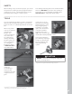
PLANNING AHEAD PLANNING AHEAD 8
PLANNING AHEAD Trex Decking: Trex® RainEscape® Deck Drainage System: » When installing any Trex decking product, especially Trex Transcend Tropicals, it is a good idea to mix and match all of the boards on the job site prior to installation to ensure an appealing mix of light and dark tones. » DO NOT combine Trex Select decking with other Trex decking products. Trex Select boards are thinner than Transcend and Enhance boards.
PLANNING AHEAD/CONTINUED PLANNING AHEAD DeckProtect® padding/rack be moved from time to time for general cleaning underneath. It should be noted that even when using DeckProtect®, burning embers could “shoot” beyond the protective mat and burn the deck. For more information about this product, please visit their website at www.deckprotect.net or call 1-800-BUY-TREX. DeckProtect® is a registered trademark of Infinite Heat Solutions.
LIGHTING LIGHTING 11
Outdoor Lighting SKUs LIGHTING & DESCRIPTION ITEM NUMBER LANDSCAPE LIGHTING Rounded Path Light Stepped Path Light Well Light Multifunction Light Spotlight* BKRDPATH2PK, BZRDPATH2PK BKSPATH2PK, BZSPATH2PK BKWELL, BZWELL BKMULTI, BZMULTI BKSPOT, BZSPOT *Includes: 36v Step-up Transformer & Female to Female Adapter DECK LIGHTING Pyramid or Flat Post Cap Light » 4" x 4" LED Post Cap Light [4.55 in x 4.55 in (115 mm x 115 mm) actual internal dimensions] Use with Trex 4 in Composite Railing Posts » 5.
HOW TO INSTALL TREX DECKLIGHTING NOTE: Avoid railing brackets and locations for deck rail lights when running wires up posts. PARTS A A Pyramid Post Cap Light B C Flat Post Cap Light D Deck Rail Light HELPFUL TIPS E x2 x2 Riser Light Recessed Deck Light Splitter » 5ft, 10ft, 20ft, 40ft, and 60ft connection/extension wires sold separately (these are male-to-male connection wires).
HOW TO INSTALL TREX DECKLIGHTING/CONTINUED General Information 3 2 » Refer to www.trex.com for instructional videos on how to install Trex Decklighting. » USE TREX TRANSFORMER ONLY. Use of any other transformer voids warranty. TRANSFORMER CAPACITY BY TYPE Type of Light 2.5A Transformer 8.3A Transformer (83 DL TRANSFORMER) (2.5 DL TRANSFORMER) Riser 285 90 Recessed 285 90 Post Cap 85 22 Deck Rail 285 90 Above listing is for maximum number of each individual types of lights.
HOW TO INSTALL TREX DECKLIGHTING/CONTINUED Timer Operation Instructions 2 1. Select the mode of operation: » Dusk to Dawn » 2–8 hours » Always “ON” » “OFF” Post Post Sleeve Program repeats daily. When power is flowing to lights, green light above POWER is on. Installing Post Cap Lights NOTE: Install post cap lights after the railing system, post sleeve skirt, and post sleeve have been installed. 1 2. Drill a 1" (25 mm) hole through post sleeve.
HOW TO INSTALL TREX DECKLIGHTING/CONTINUED 8. Line up polycarbonate 8 lens with fixture housing. Twist onto fixture base. Continue until all wiring from lights are attached to splitters as well as connector wires are attached in between splitters. (See Making Connections section for details.) 1 2 NOTE: DO NOT install riser light or deck rail light into top or bottom rails or balusters.
HOW TO INSTALL TREX LANDSCAPELIGHTING PARTS B A HELPFUL TIPS C D E Spotlight Stepped Path Light Round Multifunction Well Light Path Light Light G H Male-to-Male Connector Wire Step-up Transformer (For use with Trex Spotlight only) Female-to-Female Adapter I J Splitter Multi-zone Transformer Adapter (For use with Trex Spotlight or for multiple dimmer zones) TOOLS NEEDED 3/4" (19 mm) WARNING: BEFORE ANY TREX LANDSCAPELIGHTING IS INSTALLED, IT IS THE INSTALLERS RESPONSIBILITY TO ENSURE THAT A
HOW TO INSTALL TREX LANDSCAPELIGHTING/CONTINUED (TREX WELL LIGHT, PATH LIGHTS, AND MULTIFUNCTION LIGHTS) TRANSFORMER CAPACITY BY TYPE Type of Light 8.3A (100W) Transformer (83 DL TRANSFORMER) 2.5A Transformer (2.5 DL TRANSFORMER) Well Light 74 23 Path Light 52 16 Wall Wash Light 52 16 Above listing is for maximum number of each individual types of lights. If mixing and matching lighting, contact Trex to determine if more than one transformer is required. Please visit Trex.
HOW TO INSTALL TREX LANDSCAPELIGHTING/CONTINUED (TREX SPOTLIGHT) 3 TRANSFORMER CAPACITY BY TYPE Type of Light 8.3A Transformer (83 DL TRANSFORMER) Spotlight 12 Female-toFemale Adapter Above listing is for maximum number of each individual types of lights. If mixing and matching lighting, contact Trex to determine if more than one transformer is required. 3. Connect opposite end of female adaptor to male connector wire. Choose appropriate length wire based on your needs.
HOW TO INSTALL TREX LANDSCAPELIGHTING/CONTINUED (TREX SPOTLIGHT) 8. Ensure that lights are all working with all wiring attached prior to burying any wire. No more than 1"–3" (25 mm–76 mm) is required. 8 1˝–3˝ (25–76 mm) HOW TO PROGRAM DIMMER REMOTE 3 A. ALWAYS keep antenna fully extended for max range. LIGHTING A B. Up/Down arrows gradually dim or brighten lighting. B C D 1. Install dimmer per instructions and make sure lights are On and working properly. 2.
HOW TO INSTALL TREX SIGNATURE CAP LIGHT Installing Post Cap Lights PARTS NOTE: Instructions shown below are for new deck installation and are shown BEFORE railing system has been installed. A 1 Post Cap Light (includes 5ft male-to-male wire) 2 » 5ft, 10ft, 20ft, 40ft, and 60ft connection/extension wires sold separately (these are male-to-male connection wires). TOOLS NEEDED 9/16" x 6" or Longer (14 mm x 152 mm) 1.
HOW TO INSTALL TREX SIGNATURE CAP LIGHT/CONTINUED 5 6 1 2 LIGHTING 5. Connect the female connector on the post cap light to this wire and, using a rubber mallet, gently tap the cap onto top of post until it is secure. 6. Turn post over and carefully fish wire through hole created in Step 3 to underside of the deck. Ensure exit point of wire under blocking will not be pinched by ALPOSTHWDECK plate. 7. Mount post per instructions.
HOW TO INSTALL TREX WEDGE DECK RAIL LIGHT Installing Post Lamps PARTS NOTE: Instructions shown below are for new deck installation and are shown BEFORE railing system has been installed. A x3 1 Wedge Deck Rail Light (includes 5ft male-to-male wire) 2 » 5ft, 10ft, 20ft, 40ft, and 60ft connection/extension wires sold separately (these are male-to-male connection wires). TOOLS NEEDED 9/16" x 6" or Longer (14 mm x 152 mm) 1.
HOW TO INSTALL TREX WEDGE DECK RAIL LIGHT/CONTINUED 6 10 7a 11 3 2 1 6. Turn post upside down and fish 5' male-to-male wire (provided) through hole in baseplate. 7a. If connecting a Wedge Deck Rail Light only, pull wire through hole. LIGHTING TIP: Insert a zip-tie loop (or small grabber tool) through 9/16" (14 mm) hole. Fish wire through loop in zip-tie. Pull wire through hole with zip-tie. 7b.
DECKING DECKING 25
Trex Decking, Porch Flooring & Fascia DESCRIPTION PROFILE 1" Square-Edge Board Actual dimensions: Transcend & Enhance: .94 in x 5.5 in x 12 ft / 16 ft / 20 ft (24 mm x 140 mm x 365 cm / 487 cm / 609 cm) Select: .82 in x 5.5 in x 12 ft / 16 ft / 20 ft (20 mm x 140 mm x 365 cm / 487 cm / 609 cm) 1" Grooved-Edge Board Actual dimensions: Transcend & Enhance: .94 in x 5.5 in x 12 ft / 16 ft / 20 ft (24 mm x 140 mm x 365 cm / 487 cm / 609 cm) Select: .82 in x 5.
DECKING AND FASCIA RECOMMENDED FASTENERS TREX PRODUCT LINES Trex Hideaway® Universal Hidden Fastener ® Trex Hideaway Connector Clip Transcend® Enhance® Select® Accents® Escapes® X X X X X X X X X X TigerClaw® TC-G Hidden Fastener X FastenMaster® TrapEase 3 Ultimate Composite Deck Screw X X X X Simpson Strong Tie Deck Drive™ DCU Composite Screw (Collated and Handdrive) X X X X ® Quick Drive Composi-Lok Deck Screw X ® Dexxter Composite Screw – 6 Lobe Drive Only X X X Spli
TREX® FASCIA INSTALLATION RECOMMENDATIONS Trex Fascia utilized around the perimeter of a deck must be gapped with the same requirements as Trex decking to allow for air flow and expansion/contraction of the fascia. The gapping requirements are as follows: WIDTH-TO-WIDTH GAP Below 40°F (4.5°C) 3/8" (10 mm) Above 40°F (4.5°C) 1/4" (6 mm) END-TO-END/END-TO-WIDTH & ABUTTING GAP End-to-End/ End-to-Width Abutting Below 40°F (4.5°C) 3/16" (5 mm) 1/2" (13 mm) Above 40°F (4.
FRAMING AND FASTENING TIPS (continued) TREX AND STATIC ELECTRICITY While this is not common, static electricity can occur on walking surfaces in dry climates or in areas where dry winds and dust-borne particles lay on the decking surfaces. Static electricity can build up on occupants walking across any composite decking surface, including Trex, then produce a small static shock if they touch a grounded metal surface such as railing, door, etc.
ROOFTOP AND SLEEPER DECK SYSTEMS A sleeper system is a substructure between a solid surface and Trex decking. Drainage, access, and airflow are critical. Water must be able to flow through and away from the deck. For repairs and removal of debris, joist system access may be necessary. Gap decking from solid object (i.e. wall) 1/4"–1/2" (6–13 mm) depending on temperature at installation (See note below for more information.
CODE COMPLIANCE Joist Spanning for Decking Trex decking meets all applicable national model building codes. The joists must be spaced on center according to the chart below. Be sure that joists are level and plumb. Trex decking must span at least three joists. For heavy items such as hot tubs, planters, etc., consult a local building engineer or inspector for span recommendations. If you want to minimize the appearance of joists through the spaces between boards, paint the top of your joists black.
GAPPING and OVERHANG You must gap Trex decking, both end-to-end and width-to-width. Gapping is necessary for drainage and the slight thermal expansion and contraction of Trex decking boards. Gapping also allows for the shrinkage of the wood joist system. » ALWAYS follow Trex-recommended gapping guidelines. » Maximum allowable perpendicular overhang for all Trex decking is 1/2" (13 mm). » All decks require air circulation to keep them dry and looking good.
STAIRS Stairway Detail » Stair treads built with Trex meet requirements by the major national building codes. Consult your local municipality for specific requirements. » Fasten stair treads continuously across at least four stringers. » See chart (at right) for center-to-center spacing of profiles. » Dress the sides of the stringers and risers with trim or Trex fascia for a finished look.
TIPS FOR INSTALLING A TREX HIDEAWAY® HIDDEN FASTENING SYSTEM Installing Angled Deck Boards in Corners G IN CK DE For Universal and Stainless Steel (Universal shown here) D AR BO Routing Square Edge Boards for Trex Hideaway Hidden Fasteners NOTE: The following Trex Square Edge decking boards (Trex Transcend, Trex Enhance, Trex Escapes, Trex Accents, and Trex Select), either 1x6 or 2x6, can be routed.
HOW TO INSTALL TREX HIDEAWAY UNIVERSAL HIDDEN FASTENERS (TREX TRANSCEND, ENHANCE, SELECT, AND ESCAPES) NOTE: See page 36 for additional instructions if installing Escapes. Installing Second Board PARTS 5 Start clip Universal fastener TOOLS NEEDED 1/4" (6 mm) NOTE: Maximum spacing of deck boards using Hideaway system is 16" (406 mm) on center. Fasteners provide 1/4" (6 mm) gap when installed correctly.
HOW TO INSTALL TREX HIDEAWAY UNIVERSAL HIDDEN FASTENERS/CONTINUED Option 2: With Deck Board Overhang (Using Square Edge Board as Final Board) 7b. Pre-drill pilot holes at 45° 7b angle from below deck surface through rim joist. Seat last board into 2 1 fasteners overhanging rim joist. Secure board with 2-1/2" (64 mm) screws using pilot holes. Position fascia board below overhanging deck board. Option 3: Face Screwing Both Decking and Fascia 8.
HOW TO REPLACE TREX BOARDS/CONTINUED INSTALLED WITH TREX HIDEAWAY UNIVERSAL FASTENERS (TREX TRANSCEND, ENHANCE, SELECT, AND ESCAPES) Insert Fasteners 3 Universal Fasteners 3. Slide a fastener for each joist into board grooves from both ends of the board. Insert Fasteners NOTE: You may have to loosen adjacent boards to slide fasteners into position. 4. Position replacement board and secure fasteners on center of each joist.
HOW TO INSTALL TREX TRANSCEND PORCH BOARDS NOTE: When installing Trex Porch boards in a non-covered environment, the porch structure should be slightly sloped to help allow for proper drainage. Joists should be sloped 1/8" (3 mm) per foot away from the house to facilitate drainage. Refer to your local building code official for recommendations BEFORE building substructure. When installing Trex Porch boards under cover of a roof, no slope is required.
HOW TO INSTALL TREX TRANSCEND PORCH BOARDS/CONTINUED Installing Last Porch board Option 1: Using Fascia Board 7a. Pre-drill pilot holes at an angle through grooved edge of porch board into ledger board. Install 2-1/2" (64 mm) screws through pilot holes to secure. Attach fascia board flush with porch board surface. 7a 1 2 NOTE: In most cases there will be additional screws that come with the Trex Hideaway Universal Hidden Fasteners.
LOCATION AND INSTALLATION OF SURFACE MOUNT POST – DECKING IMPORTANT NOTES: » EACH POST MUST BE ATTACHED AS SHOWN TO ENSURE A CODE-COMPLIANT AND SAFE INSTALLATION. » ALWAYS REFER TO YOUR LOCAL BUILDING CODE OFFICIAL PRIOR TO INSTALLING ANY RAILING SYSTEM TO ENSURE ALL CODE AND SAFETY REQUIREMENTS ARE MET. TREX CANNOT BE HELD RESPONSIBLE FOR IMPROPER OR NON-RECOMMENDED INSTALLATIONS.
LOCATION AND INSTALLATION OF SURFACE MOUNT POST – DECKING/ CONTINUED Line Post Installation 3 Cross bracing frame /4" cm) 7-18 (1 .4 Cross bracing frame Attach posts using four 3/8" x 6" (1 cm x 15.2 cm) hex cap bolts, washers, and nuts, along with aluminum back plate on underside of blocking. If the project requires IRC compliance, this back plate MUST be installed under the decking to ensure this will meet code compliance.
LOCATION AND INSTALLATION OF SURFACE MOUNT POST – DECKING/ CONTINUED Install Railing System of Choice attachment of brackets to guide blocks. Use a drill bit slightly smaller in size than that of screw being installed. NOTES: » Quantity of 18 self-tapping screws are provided to cover all types of Trex railing bracket installations (Transcend, Signature [formerly Reveal], and Select). Thus depending on the type railing being installed, you may have screws that are not used.
LOCATION AND INSTALLATION OF POST MOUNTS – CONCRETE/CONTINUED 6 2 7 notch 2. Clean out holes to remove all concrete dust. 3 6. Location of top guide block will vary slightly based on type and height of railing being installed. Determine this measurement and place top guide block in location where top bracket for desired railing would be approximately on center of the top railing bracket location. 7.
HOW TO INSTALL JOIST MOUNT POSTS Joist Mount Post for Trex Composite Post Sleeve SKU CPJMNTPOST63 » (1) Joist Mount Post » (2) Guide blocks » (2) 10 x 1" (2.5 cm) Self-tapping screws » (18) #8-15 x 1-1/4" (3.
INSIDE MOUNT (FRONT RIM PLATE - BETWEEN JOISTS WITH BLOCKING) Simpson ML26Z Blocking 2"x 8" (51 mm x 203 mm) Simpson LUS28Z Simpson L70Z Trex Bolts 1/2" x 8" (13 mm x 203 mm), Nuts, and Washers INSIDE MOUNT (FRONT RIM PLATE - NEXT TO JOIST) Front Rim Joist Post Simpson L70Z Trex Bolts 1/2" x 8" (13 mm x 203 mm), Nuts, and Washers Simpson LUS28Z Simpson DTT2Z SIDE VIEW Post Front Rim Joist HOW TO INSTALL DECKING NOTE: If a joist hanger is in this location, it must be removed so post mount will f
INSIDE MOUNT (SIDE JOIST) » TREX SUPPLIES (2) HG 1/2" X 8" (13 mm x 203 mm) BOLTS, NUTS, AND WASHERS. » CUSTOMER MUST SUPPLY ADDITIONAL HG 1/2" X 8" (13 mm x 203 mm) BOLTS, NUTS, AND WASHERS.
INSIDE MOUNT (CORNER) » TREX SUPPLIES (2) HG 1/2" X 8" (13 mm x 203 mm) BOLTS, NUTS, AND WASHERS. » CUSTOMER MUST SUPPLY ADDITIONAL HG 1/2" X 8" (13 mm x 203 mm) BOLTS, NUTS, AND WASHERS. Blocking 2"x 8" (51 mm x 203 mm) min NOTE: If a L70Z is in this location, it must be removed so post mount will fit properly.
FASCIA MOUNT (FRONT RIM PLATE - NEXT TO JOIST) » FOR USE WITH TREX REVEAL 6' RAILING SECTIONS ONLY. » TREX SUPPLIES (2) HG 1/2" X 8" (13 mm x 203 mm) BOLTS, NUTS, AND WASHERS. TOP VIEW Trex Fascia Post Front Rim Joist Trex Fascia Mount Kit (L Bracket) Trex Bolts 1/2" x 8" (13 mm x 203 mm), Nuts, and Washers Simpson DTT2Z Simpson LUS28Z NOTE: If a joist hanger is in this location, it must be removed so post mount will fit properly.
FASCIA MOUNT (SIDE JOIST - WITH BLOCKING) » TREX SUPPLIES (2) HG 1/2" X 8" (13 mm x 203 mm) BOLTS, NUTS, AND WASHERS. » CUSTOMER MUST SUPPLY ADDITIONAL HG 1/2" X 8" (13 mm x 203 mm) BOLTS, NUTS, AND WASHERS.
FASCIA MOUNT (OUTSIDE FRAME CORNER) » 3/4" (19 mm) FASCIA MUST BE USED, OR BOLTS MUST BE CUT DOWN. » INSTALL POST TIGHTLY ON RIM JOIST FIRST – NUTS WILL BE INACCESSIBLE LATER. » MUST USE TREX FASCIA MOUNT CORNER BRACKET KIT.
COMPOSITE POST APPLICATIONS Installation of Guide Blocks and Railing NOTE: Pre-drilling is not required but is optional for attachment of guide blocks to post. Use a drill bit slightly smaller in size than that of screw being installed. 2 1 notch 6. Place or rest bottom aluminum guide block on bottom of post. Place guide on post so that notch is on a side that does not require railing to be attached. 7.
RAILING RAILING 52
2a 3a RAILING— a lot easier than it looks Selecting the right railing is pretty easy, but 1 4 1+2 each Trex railing line is a little different. Please read the system descriptions at the top of each product section so you can choose exactly which railing components you need to complete your design. For additional guidance, the chart to the 2b 3 3 left depicts each railing system's components.
Signature Aluminum Railing (previously Reveal Railing) SKUs Choose either Signature posts or Trex post sleeves, caps and skirts for steps 1 & 2. Pair with a rail & baluster kit (step 3). STEP 1+2 DESCRIPTION COMPONENT Aluminum Post with Cap & Skirt 2.5" x 2.5" x 37" Post—Horizontal (IRC Compliant) Aluminum Crossover Post 2.5" x 2.5" x 43" Post—Horizontal (IRC Compliant) ITEM NUMBER XXAL252537RCAP [2.5 in x 2.5 in x 37 in (63 mm x 63 mm x 939 mm) actual dimensions] XXAL252543RCAP [2.5 in x 2.
Transcend Railing SKUs Transcend is either a 5-step or 3-step process. Choose Trex post sleeves, caps and skirts (steps 1 & 2). Then choose each component separately for a custom design (5-step). STEP DESCRIPTION COMPONENT Top & Bottom Rails 3a In this step, two rails (1 top, 1 bottom) must be selected. 3b ITEM NUMBER 6' Crown Top Rail 8' Crown Top Rail XXCROWNTR06 XXCROWNTR08 6' Universal Top/Bottom Rail 8' Universal Top/Bottom Rail XXUNIVTBR06 XXUNIVTBR08 [6' Rail: 67.
Select Railing SKUs Select is a 3-step process. Choose Trex post sleeves, caps and skirts (steps 1 & 2) and a rail & baluster kit (step 3).
TREX TRANSCEND RAILING NOTES: » TREX TRANSCEND RAILINGS ARE DESIGNED TO BE INSTALLED OVER THE DECKING FRAME OR ON INSIDE OF RIM JOIST. NOTCHING OF PRESSURE-TREATED POSTS OR POSTS INSTALLED ON OUTSIDE OF RIM JOIST ARE NOT ALLOWED. » All Trex Transcend railing lengths are manufactured at ON CENTER dimensions (spanning from center of each post): 67-5/8" (1718 mm) for 6' (1.83 m) on center, and 91-5/8" (2353 mm) for 8' (2.44 m) on center.
TREX TRANSCEND RAILING CONFIGURATIONS Note: See specific installation instructions for attachment of Trex post mounts or Trex Joist Mount Posts prior to installing any railing. Cutting post sleeves is NOT required. A. Pressure-treated post/Trex post sleeve, Trex post mount/Trex post sleeve*, or Joist Mount Post/Trex post sleeve* (INSIDE MOUNT ONLY) B. Crown rail C. Universal bottom D. Trex balusters See page 59 for “How to Install Standard Railing”.
HOW TO INSTALL STANDARD RAILING TREX TRANSCEND Installing Railing Support Brackets (RSBs) Option 1: Without TrexExpress railing template 3a 3b 1 2 3 4 35-1/16\ 35-1/16" (891 (89.1mm) cm) or 41-1/16" 41-1/16\ (1043 mm) 5-1/2" (140 mm) Read all instructions BEFORE installation. Important: Post sleeves are NOT to be cut for this design style. Installing PressureTreated Posts 1 » Posts are to be installed 2" x 8" (51 mm x 6' (1.83 m) or 8' 1" (25 mm) min. 203 mm) min. (2.
HOW TO INSTALL STANDARD RAILING/CONTINUED TREX TRANSCEND Cutting Railings Attaching Bottom Rail (Universal Rail), Adding Weep Holes 4 4. Measure between posts and cut rails to same length. 6b 6a NOTES: » If using optional rail gaskets, subtract 1/16" (1.6 mm) from each end. » Attach baluster spacers to railing before cutting to allow for cleaner cut and less work.
HOW TO INSTALL STANDARD RAILING/CONTINUED TREX TRANSCEND Option 10. Slide baluster spacer up and snap into top rail. Place optional top rail gaskets on each end of rail. 10 2 Attaching Post Caps and Installing New Foot Blocks 11. Secure post caps with silicone or PVC adhesive. Attach New foot block per foot block instructions. 11 2 2 1 Note: Clean-up any excess adhesive before drying. 3 HOW TO INSTALL COCKTAIL RAILING TREX TRANSCEND 4. Cutting Railings See instructions on page 60. 5.
HOW TO INSTALL COCKTAIL RAILING/CONTINUED TREX TRANSCEND universal rails from underside of railing into bottom of decking board, with 2" (51 mm) pan-head screws (not provided) at an angle every 16" (406 mm) on center. IMPORTANT NOTES: » If using Select decking, USE maximum length 1-3/4" (44 mm) screw and NOT 2" (51 mm) screw. » Screws that are used for attachment of decking board to railing MUST be attached at angle to prevent screw from penetrating through the top of decking board. 11.
HOW TO INSTALL TRADITIONAL RAILING/CONTINUED TREX TRANSCEND 10. Measure between posts and cut 2" x 4" (51 mm x 102 mm) to length. Place 2" x 4" (51 mm x 102 mm) on universal rail. Attach board to rail with 2" (51 mm) pan-head screws (not provided) every 16" (406 mm) on center. 10 12 Optional 1 12. Slide baluster spacer up and snap into universal rail. 11.
HOW TO INSTALL ROUND OR SQUARE ALUMINUM BALUSTERS/CONTINUED TREX TRANSCEND NOTE: To determine weep hole locations, temporarily place lower baluster spacer beside lower rail and mark inside of channel in locations accordingly. 8. Snap baluster spacer into bottom rail. Place inverted baluster spacer on top of first baluster spacer. 10 11 2 8 1 Attaching Top Rail, Aluminum Baluster Adaptor Strip, and Balusters and Bottom Baluster Spacer 9. Place crown or rail on 9 RSBs with balusters in rail channels.
HOW TO INSTALL STANDARD GLASS PANEL RAILING/CONTINUED TREX TRANSCEND TEMPERED GLASS PANEL DIMENSIONS » » Attaching Top (Crown) Rail 9. Place top rail over 9 RSB brackets and glass panel. Attach top rail to RSB with three self-tapping screws provided (use x2 threeouter holes; do 2 Hole not use hole in RSB RSB that is closest to post). 2 If two hole bracket is included, attach with two self-tapping holes (provided). 36" (914 mm) high rail: 1/4" x 30" x 63-1/2" max.
HOW TO INSTALL COCKTAIL STYLE GLASS PANEL RAILING TREX TRANSCEND 5. Attaching Foot Block See instructions on page 60. 6. Attaching Bottom Rail (Universal Rail), Adding Weep Holes See instructions on page 60. 7-8. Attaching Weatherstripping and Positioning Panel See instructions on page 65. Attaching Top Rail NOTES: Read all instructions BEFORE installation. » You must purchase the 1/4" (6 mm) tempered glass panels. See dimensions below. » Glass panels ONLY for use with maximum 6' (1.
HOW TO ATTACH COCKTAIL STYLE GLASS PANEL RAILING/CONTINUED TREX TRANSCEND 12. Secure deck board to Universal rail with 2" (51 mm) pan head screws (not provided) approximately every 16" (406 mm) on center at an angle. (DO NOT overtighten. Attach from underside of railing into bottom of decking board.) 14. Attach deck board to post (ensure that screws are attached to wood post) with Trex recommended composite screws (quantity of 2 per each board end). 12 14 15.
HOW TO ATTACH TRADITIONAL STYLE GLASS PANEL RAILING/CONTINUED TREX TRANSCEND 1. Installing Pressure-Treated Posts See instructions on page 59. 11 12 2. Installing Post Sleeve Skirts and Post Sleeves See instructions on page 59. 3. Installing Railing Support Brackets (RSBs) See instructions on page 59. 4. Cutting Railings See instructions on page 60. 5. Attaching Foot Block See instructions on page 60. 6. Attaching Bottom Rail (Universal Rail), Adding Weep Holes 11.
HOW TO INSTALL ON-AN-ANGLE RAILING TREX TRANSCEND (CROWN AND UNIVERSAL RAILING) NOTE: Trex railing brackets are designed to be installed up to a 45° angle. 4x4 6x6 » Small angles (1° - 30°). Both 4" x 4" (102 mm x 102 mm) or 6" x 6" (152 mm x 152 mm) post sleeves work well. » Large angles (31° - 45°). USE ONLY 6" x 6" (152 mm x 152 mm) post sleeves when installing on flat side. » 45° angles using 4" x 4" (102 mm x 102 mm) post sleeves MUST use Transcend Bird’s Mouth brackets.
HOW TO INSTALL CROWN AND UNIVERSAL BIRD'S MOUTH RAILING/CONTINUED TREX TRANSCEND Measuring and Cutting Rails Installing Railings to RSB's 6 6. Attach with self-tapping screws (provided). 4 4. Measure from corner-to-corner between posts. Mark 45° cuts on rails with template on assembly tool. Center of “V’s” is the distance from corner-to-corner for posts. Using Miter Box Saw to Cut Rails NOTE: Subtract 1/16" (1.6 mm) from each end to accommodate rail gaskets. Attaching Top and Bottom RSBs 1.
HOW TO INSTALL CROWN AND UNIVERSAL STAIR RAILING/CONTINUED TREX TRANSCEND 2b. Set bottom and top rail along the nose of the stair treads, ensuring baluster holes are placed evenly. Also allow for a minimum of 1 1/2" at each end of rail for bracket placement and baluster clearance. Cut rails on marks. 2b 3. Position bottom rail between posts and slide TrexExpress™ railing assembly template into position with bottom rail outline on template aligned with end of bottom rail.
HOW TO INSTALL CROWN AND UNIVERSAL STAIR RAILING/CONTINUED TREX TRANSCEND Attaching RSBs to UPPER Posts Attaching Top Rail 11a. Place top rail of choice (Crown rail shown here) on RSB's in rail channel and attach with 3 self-tapping screws (provided). Use the three outer holes in RSB to attach screws. 6 3 1 1 4 2 11a 1 Lower Post Location Top Rail Upper Post Location Top Rail 6. Attach upper and lower RSBs to top post, flat side DOWN. Remove template.
TREX SIGNATURE® (FORMERLY REVEAL®) RAILING NOTES: » SIGNATURE POSTS CANNOT BE USED WITH SIGNATURE TRADITIONAL OR SIGNATURE COCKTAIL DESIGNS, ONLY PRESSURE-TREATED POSTS/ POST SLEEVES CAN BE USED. REFER TO DETAILED INSTRUCTIONS FOR MORE INFORMATION. » SIGNATURE RAILINGS ARE DESIGNED TO BE ATTACHED WITH POSTS INSTALLED AT A CLEAR SPAN OF 6' (1.83 M) OR 8' (2.44 M). » IF INSTALLING AT EXACT SPAN LENGTHS OF 6' (1.83 M) OR 8' (2.
INSTALLING SIGNATURE POSTS AND/OR SIGNATURE CROSSOVER POSTS ON WOOD OR CONCRETE IMPORTANT NOTES: » EACH POST MUST BE ATTACHED AS SHOWN TO ENSURE A CODECOMPLIANT AND SAFE INSTALLATION. » SIGNATURE POSTS CANNOT BE USED WITH SIGNATURE TRADITIONAL OR SIGNATURE COCKTAIL DESIGNS, ONLY Pressure-treated POST/POST SLEEVES CAN BE USED. REFER TO DETAILED INSTRUCTIONS FOR MORE INFORMATION.
INSTALLING SIGNATURE POSTS AND/OR SIGNATURE CROSSOVER POSTS ON WOOD OR CONCRETE/CONTINUED NOTES: » Rim joist removed to show proper attachment of hardware. » Metal backplate is only required for 2.5" (64 mm) post in IRC installations. (Consult local code official for more information.) 5. Insert (2) stainless 5 steel barrier strips under mounting bolt holes. Use composite shims or similar material (not provided) if posts are not plumb.
TREX SIGNATURE RAILING CONFIGURATIONS Standard Cutting posts/post sleeves is NOT required. A. Signature post, pressure-treated post or Trex Post Mounts* with Trex Transcend post sleeves, or Trex Joist Mount Posts*. B. Signature top rail C. Signature bottom rail D. Signature balusters See page 78 for “How to Install Standard Railing”. B A D C *NOTE: See specific installation instructions for attachment of Trex post mounts or Trex Joist Mount Posts prior to installing any railing.
BRACKET HARDWARE – HORIZONTAL APPLICATIONS (INCLUDING HORIZONTAL SWIVEL BRACKETS) TREX SIGNATURE HORIZONTAL RAILING HARDWARE AA. Lower rail bracket BB. Lower rail bracket cover CC. Upper rail bracket cover DD. Upper rail bracket AA BB CC DD FOOT BLOCK COMPONENTS EE. Foot block base FF. Foot block support FF EE HORIZONTAL SWIVEL HARDWARE GG. HH. II. JJ. KK. LL.
HOW TO INSTALL HORIZONTAL RAILING TREX SIGNATURE STANDARD Attach Brackets Using Signature Posts Attach Brackets Using Pressure-treated Posts and Post Sleeves TIP: Use a clamp to help hold brackets in place while fastening with screws. 1a TIP: Use a clamp to help hold brackets in place while fastening with screws. 1b 6 5 1-1/2" (3.8 cm) 2" Post 1-3/8" (3.5 cm) 2-1/2" Post 1-7/8" (4.8 cm) 1 2 1a. If using 2" post, for both post-to-post and post-to-crossover post configurations, measure 1-1/2" (3.
HOW TO INSTALL HORIZONTAL RAILING/CONTINUED TREX SIGNATURE STANDARD NOTES: » SIGNATURE RAILINGS ARE DESIGNED TO BE ATTACHED WITH POSTS INSTALLED AT A CLEAR SPAN OF 6' (1.83 M) OR 8' (2.44 M). » IF INSTALLING AT EXACT SPAN LENGTHS OF 6' (1.83 M) OR 8' (2.44 M), AND USING POST-TO-POST CONFIGURATION, THE BOTTOM RAIL WILL NOT NEED TO BE CUT, BUT THE TOP RAIL WILL NEED TO BE MEASURED (MAKING SURE BALUSTERS LINE UP VERTICALLY) AND CUT.
HOW TO INSTALL HORIZONTAL RAILING/CONTINUED TREX SIGNATURE STANDARD Cutting Top Rail Option 1: For Post-to-Post Configuration KEYKEY Mark Cut 5a Cutting Top Rail KEYKEY Mark Cut 5c t d pos andar St ost over p Cross ost ard p Stand Top rail Top rail 1/4" (0.6 cm) 3/4" (1.9 cm) 1/4" (0.6 cm) 5a. Cut each end of top rail 1/4" (0.6 cm) shorter than mark to allow for fit into top rail brackets.
HOW TO INSTALL HORIZONTAL RAILING/CONTINUED TREX SIGNATURE STANDARD Attaching Center Baluster to Bottom Rail 10 Center balluster slot 11 1/2" (1.3 cm) 2 8 8. Attach shorter, center baluster in center slot in bottom rail using two #8 x 1-1/4" (3.2 cm) screws (provided). Attaching Bottom Rail Cover and Bottom Rail to Brackets 9 7/64" (.28 cm) 1 10. Set bottom rail into bottom brackets. Tabs on brackets will be inside of bottom rail (not shown when railing is attached).
HOW TO INSTALL HORIZONTAL RAILING/CONTINUED TREX SIGNATURE STANDARD Attach Upper Railings 15. For crossover post configuration, fasten upper rail to crossover post by installing screws diagonally through upper rail into post using two self-tapping screws each side (provided). 13 1 1 2 7/64" 1 (.28 cm) 2 1 3 16. Attach “crowned” upper rail cover to upper rail by aligning cover on one side of rail. Then starting from one end of rail, snap cover onto opposing slot working down length of rail.
HOW TO INSTALL HORIZONTAL RAILING/CONTINUED TREX SIGNATURE STANDARD Attachment of Bracket Covers, Skirts, and Caps 17 18 1 Signature post 1 2 2 17. Attach corresponding bracket covers over opening in upper and bottom rails. 18. Attach provided post skirt to bottom of posts when using Signature posts. 19 20 1 2 Signature post Post sleeve 1 3 19. Attach post caps to Signature posts. (Use of rubber mallet may be required for secure attachment.) 20.
INSTALLATION OF HORIZONTAL SWIVEL BRACKETS TREX SIGNATURE STANDARD Attach Swivel Bracket Base using Signature Posts TIP: Use a clamp to help hold brackets in place while fastening with screws. Attach Brackets Using Pressure-treated Posts and Post Sleeves TIP: Use a clamp to help hold brackets in place while fastening with screws. 1b 1a 5 2" Post 1-1/2" (3.8 cm) 1-3/8" (3.5 cm) 6 2-1/2" Post 1 1-7/8" (4.8 cm) 2 1a.
INSTALLATION OF HORIZONTAL SWIVEL RAILING TREX SIGNATURE STANDARD NOTES: » WHEN USING SIGNATURE HORIZONTAL SWIVEL BRACKETS BOTH BOTTOM AND TOP RAILS WILL NEED TO BE MEASURED AND CUT TO APPROPRIATE LENGTHS. Cutting Bottom Rail and Bottom Rail Cover 2 » HORIZONTAL SWIVEL BRACKETS CAN BE USED UP TO A 50º ANGLE FOR SIGNATURE RAILINGS. » WHEN USING HORIZONTAL SWIVEL BRACKETS VERY IMPORTANT TO LAY OUT LOCATION AND ORIENTATION OF POSTS AND SWIVEL BRACKETS BEFORE INSTALLING SWIVEL BRACKETS.
INSTALLATION OF HORIZONTAL SWIVEL RAILING/CONTINUED TREX SIGNATURE STANDARD Cutting Top Rail Cutting Top Rail Insert and Cover Option 1: For Post-to-Post Configuration 5a KEYKEY Mark Cut 6 ost ard p Stand ost ard p Stand Top rail Top rail 3/4" (1.9 cm) 1/4" (0.6 cm) 3/4" (1.9 cm) 1/4" (0.6 cm) 6. 5a. Cut top rail to the measurement between the top swivel brackets. For standard-post-to-standardpost configurations this would be same dimensions as that of the bottom rail. 7.
HOW TO INSTALL SIGNATURE COCKTAIL RAILING TREX SIGNATURE Cutting Post and Post Sleeve 2. 3. 2 Mark and cut post and post sleeve measuring from deck surface: » 36-1/32" (915 mm) for 36" (914 mm) height. » 42-1/32" (1068 mm) for 42" (1067 mm) height. 36-1/32" (915 mm) or 42-1/32" (1068 mm) Installing Horizontal Fixed Brackets See instructions on page 78. Important: ONLY for use with pressure-treated 4 x 4 post (3.5" nominal square) and 4" x 4" (102 mm x 102 mm) post sleeve.
HOW TO INSTALL SIGNATURE COCKTAIL RAILING/CONTINUED TREX SIGNATURE 12. Secure boards to top rail using Signature Cocktail Bracket (sold separately). Ensure that there is a bracket at each end of the railing section, then space brackets approximately every 24" and attach with 4 screws provided. 13. Use scarf cut for posts where two deck boards meet. 12 1 2 13 NOTES: » If installing in weather below 40°F (4.5°C), leave 1/8" (3 mm) gap between deck boards.
HOW TO INSTALL SIGNATURE TRADITIONAL RAILING/CONTINUED TREX SIGNATURE 11. Place 2" x 4" (51 mm x 102 mm) on Signature top rail. 11 13. Pre-drill a pilot hole and toenail 2-1/2" (6.4 cm) screw at each end of 2" x 4" (5.1 cm x 10.2 cm) into post on back side of rail (side not facing decking). 1 1 12. Secure 2" x 4" (51 12 mm x 102 mm) to top rail using Signature Cocktail Bracket (sold separately).
BRACKET HARDWARE – STAIR APPLICATIONS (INCLUDING STAIR SWIVEL BRACKETS, STAIR CROSSOVER BRACKET, AND COMPOUND SWIVEL BRACKETS) TREX SIGNATURE FIXED BRACKET – STAIR HARDWARE AA. Bottom Stair Bracket and Cover – Lower Rail BB. Top Stair Bracket and Cover – Lower Rail CC. Fastener Pack DD. Bottom Stair Bracket and Cover – Upper Rail EE. Top Stair Bracket and Cover – Upper Rail SWIVEL BRACKET – STAIR HARDWARE SIGNATURE RAILING FF. GG. HH. II.
BRACKET HARDWARE – STAIR APPLICATIONS (INCLUDING STAIR SWIVEL BRACKETS, STAIR CROSSOVER BRACKET, AND COMPOUND SWIVEL BRACKETS)/CONTINUED TREX SIGNATURE COMPOUND SWIVEL BRACKET – STAIR HARDWARE JJ. Compound Swivel Top Rail Bracket and Cover – Stair KK. Compound Swivel Bottom Rail Bracket and Cover – Stair LL. Fastener Covers MM. Fastener Pack SWIVEL CROSSOVER BRACKET KIT – STAIR HARDWARE NN. Swivel Crossover Bracket – Stair OO.
HOW TO INSTALL SIGNATURE STAIR POSTS AND STAIR RAILING SIGNATURE RAILING TREX SIGNATURE 92 IMPORTANT NOTES: » SIGNATURE POSTS CANNOT BE USED WITH SIGNATURE TRADITIONAL OR SIGNATURE COCKTAIL STAIR DESIGNS, ONLY PRESSURETREATED POST/POST SLEEVES CAN BE USED. REFER TO DETAILED INSTRUCTIONS FOR MORE INFORMATION. » ALL SIGNATURE STAIR INSTALLATIONS REQUIRE THE USE OF 53" (134.6 CM) STAIR POST, MEASURED AND CUT TO APPROPRIATE LENGTH IF REQUIRED.
ATTACHING STAIR BRACKETS (FIXED STAIR, STAIR SWIVEL, AND COMPOUND SWIVEL) TO SIGNATURE POSTS AND PRESSURETREATED POST AND POST SLEEVES TREX SIGNATURE NOTES: » All Signature fixed stair brackets work ONLY with stair slopes of 32°-37°. » Illustrations shown are representations when using Signature post, but same rules apply if using pressure-treated posts and post sleeves. » Use a clamp to help hold stair brackets in place while fastening with screws.
ATTACHING STAIR BRACKETS (FIXED STAIR, STAIR SWIVEL, AND COMPOUND SWIVEL) TO SIGNATURE POSTS AND PRESSURETREATED POST AND POST SLEEVES/CONTINUED TREX SIGNATURE Installing Upper Fixed Stair Brackets Mounting Holes 7 4 Required distance per railing height Required distance per railing height 2 7. Center upper stair swivel bracket on post below the marked line and attach using four self-tapping screws (provided). 4. Measure up required dimension for 36” (91.4 cm) tall railing or 42” (106.
ATTACHING STAIR BRACKETS (FIXED STAIR, STAIR SWIVEL, AND COMPOUND SWIVEL) TO SIGNATURE POSTS AND PRESSURETREATED POST AND POST SLEEVES/CONTINUED TREX SIGNATURE When using Stair Swivel and Compound Swivel Brackets: 1b When using Stair Swivel or Compound Swivel Brackets: 2b 1b. With brackets in correct swivel locations, measure distance from inside of swivel bracket to inside of swivel bracket.
ATTACHING STAIR BRACKETS (FIXED STAIR, STAIR SWIVEL, AND COMPOUND SWIVEL) TO SIGNATURE POSTS AND PRESSURETREATED POST AND POST SLEEVES/CONTINUED TREX SIGNATURE When using Stair Swivel and Compound Swivel Brackets: 4 1 2 5c. Place two balusters into lower rail at each end closest to post. 5c 1 4. Set bottom stair rail into bottom stair rail brackets. Attach bottom stair rail to bottom stair bracket using two self-tapping screws (provided) on each side of bracket.
ATTACHING STAIR BRACKETS (FIXED STAIR, STAIR SWIVEL, AND COMPOUND SWIVEL) TO SIGNATURE POSTS AND PRESSURETREATED POST AND POST SLEEVES/CONTINUED TREX SIGNATURE Attaching Stair Crossover Swivel Bracket to Post 8 6 1/4" (0.6 cm) Bracket cover 6. Insert stair crossover swivel bracket into post. NOTE: Keep the bracket cover on when inserting this into post, this will cover the screw attachment area. 8.
ATTACHING STAIR BRACKETS (FIXED STAIR, STAIR SWIVEL, AND COMPOUND SWIVEL) TO SIGNATURE POSTS AND PRESSURETREATED POST AND POST SLEEVES/CONTINUED TREX SIGNATURE Cutting Top Stair Rail and Rail Insert Cutting Top Stair Rail and Insert Option 1: For Stair-Post-to-Stair-Post Configuration Option 2: For Stair-Post-to-Stair-Crossover-Post Configuration When Using Fixed Stair Brackets: When Using Fixed Stair Brackets: KEYKEY Mark Cut 10a St Top stair rail 1/4" (0.
ATTACHING STAIR BRACKETS (FIXED STAIR, STAIR SWIVEL, AND COMPOUND SWIVEL) TO SIGNATURE POSTS AND PRESSURETREATED POST AND POST SLEEVES/CONTINUED TREX SIGNATURE Cutting Top Stair Rail and Rail Insert 14 Option 3: For Stair-Crossover-Post-to-Stair-Crossover-Post Configuration 12a KEYKEY Mark Cut ost over p Cross 2 1 ost over p Cross 3 Top stair rail 12a. Cut each end of the top stair rail along with rail insert on the mark line to allow for fit into the crossover post bracket on each side.
ATTACHING STAIR BRACKETS (FIXED STAIR, STAIR SWIVEL, AND COMPOUND SWIVEL) TO SIGNATURE POSTS AND PRESSURETREATED POST AND POST SLEEVES/CONTINUED TREX SIGNATURE Attaching Upper Stair Rails 16 18 19 1 2 2 17a. For stair post to post configuration, attach top stair rail to top stair bracket (all types) using two self-tapping screws (provided) on each side of stair bracket. Reveal post 1 16. Working from one end of upper stair rail, snap balusters into upper stair rail working down length of rail.
HOW TO INSTALL SIGNATURE COCKTAIL STAIR RAILING TREX SIGNATURE How to Measure Top Stair Railings (WHEN REQUIRED) 4. See instructions on page 96. Cutting Top Stair Rail and Rail Insert When using Fixed Stair Brackets KEYKEY Mark Cut 5a ost ard p Stand ost ard p Stand Top stair rail IMPORTANT NOTES: » Only for use with pressure-treated 4 x 4 post (3.5" nominal square) and 4" x 4" (102 mm x 102 mm) post sleeve.
HOW TO INSTALL SIGNATURE COCKTAIL STAIR RAILING TREX SIGNATURE /CONTINUED Cutting Post and Post Sleeve and Attaching Deck Board to Top Rail 9. Cut post and post sleeves at proper angle so these are flush with the top of the top brackets and/or top rail cover. BE CAREFUL to not CUT brackets. 12. Use scarf cut for posts where two deck boards meet. 9 12 NOTES: » If installing in weather below 40°F (4.5°C), leave 1/8" (3 mm) gap between deck boards.
HOW TO INSTALL SIGNATURE TRADITIONAL STAIR RAILING TREX SIGNATURE Cutting Bottom Stair Rail, Bottom Stair Rail Cover 9. See instructions on page 95. Attachment of Bottom Stair Rail Cover and Bottom Stair Rail to Brackets 10. See instructions on page 95. How to Measure Top Stair Railings When Using Fixed Stair Brackets 11. See instructions on page 96. Important: ONLY use for use with pressure-treated 4 x 4 post (3.5" nominal square) and 4" x 4" (102 mm x 102 mm) or 6" x 6" post sleeve.
HOW TO INSTALL SIGNATURE TRADITIONAL STAIR RAILING/CONTINUED TREX SIGNATURE 19. Place 2" x 4" (51 mm x 102 mm) on Signature top stair rail. 19 20. Secure 2" x 4" (51 mm x 102 mm) to top rail using Signature Cocktail Bracket (sold separately). Ensure that there is a bracket at each end of the railing section, then space brackets approximately every 24" and attach with 4 screws provided. 20 1 2 NOTE: Predrilling before attachment is recommended. 21. Pre-drill a pilot hole and toenail 2-1/2" (6.
INSTALLING ALUMINUM GATE » SEE PAGE 56 FOR SKU NUMBERS 5 1 1 1 1 1 1 2 1. Measure opening between posts (gates can be customized to fit nearly any opening up to 48" [1219 mm] wide). 2. Subtract 1-7/8" (48 mm) from above measurement. This will allow for proper gapping and location of gate. NOTE: If widths do fall on a baluster, cut baluster flush at top and bottom prior to cutting panel. 6 1 3 5. Adjust posts so that cut marks do not fall on a baluster.
INSTALLING ALUMINUM GATE/CONTINUED 10 8 4" max (102 mm) 10. Place gate in opening on blocks. Sweep between bottom of gate and top of deck cannot exceed 4" (102 mm) per IRC/IBC code regulations. Ensure bottom gate posts will be high enough to clear skirts on bottom of deck posts. 11. Make sure posts are plumb 11 1 and gate is level. Attach longer side of hinges to post using appropriate hardware for type of post installed. Install hinge cover. 8.
TREX SIGNATURE (FORMALLY REVEAL) PANELS NOTES: » SIGNATURE RAILINGS ARE DESIGNED TO BE ATTACHED WITH POSTS INSTALLED AT A CLEAR SPAN OF 6' (1.83 M) OR 8' (2.44 M). » IF INSTALLING AT EXACT SPAN LENGTHS OF 6' (1.83 M) OR 8' (2.44 M), AND USING POST-TO-POST CONFIGURATION, THE BOTTOM RAIL WILL NOT NEED TO BE CUT, BUT THE TOP RAIL WILL NEED TO BE MEASURED AND CUT. » IF INSTALLING AT EXACT SPAN LENGTHS OF 6' (1.83 M) OR 8' (2.
BRACKET HARDWARE – HORIZONTAL APPLICATIONS (INCLUDING HORIZONTAL SWIVEL BRACKETS) TREX SIGNATURE HORIZONTAL RAILING HARDWARE AA. Lower rail bracket BB. Lower rail bracket cover CC. Upper rail bracket cover DD. Upper rail bracket AA BB CC DD FOOT BLOCK COMPONENTS EE. Foot block base FF. Foot block support FF EE HORIZONTAL SWIVEL HARDWARE GG. HH. II. JJ. KK. LL.
HOW TO INSTALL PANELS TREX SIGNATURE Attach Brackets Using Pressure-Treated Posts and Post Sleeves Attach Brackets Using Signature Posts TIP: Use a clamp to help hold brackets in place while fastening with screws. 1a TIP: Use a clamp to help hold brackets in place while fastening with screws. 1b 1-1/2" (38 mm) 2" Post (51 mm) 1-3/8" (35 mm) 2-1/2" Post (64 mm) 6 5 1-7/8" (48 mm) 1 2 1a.
HOW TO INSTALL PANELS/CONTINUED TREX SIGNATURE How to Measure and Cut Bottom and Top Railings of Signature Panel (When REQUIRED) 1 Cutting Top Rail Option 1: For Post-to-Post Configuration KEYKEY Mark Cut 3a Top rail ost ard p Stand ost ard p Stand 1/4" (6 mm) 1. Position panel between posts and align with bottom bracket. Align center baluster with middle of span between posts (this will allow for equal spacing between end balusters and each post). Mark bottom and top rail at each end.
HOW TO INSTALL PANELS/CONTINUED TREX SIGNATURE Cutting Top Rail Install Signature Panel Option 3: For Crossover Post-to-Crossover Post Configuration KEYKEY Mark Cut 3c Top rail 7 6 ost over p Cross ost over p Cross 3/4" (19 mm) 3/4" (19 mm) 6. Break or cut the bottom tab off the bottom brackets. 7. Put a dab of silicone in the basket of the bottom bracket to prevent rattle. 8 3c.
HOW TO INSTALL PANELS/CONTINUED TREX SIGNATURE 11 15 14 2 1 1 2 Signature post Post sleeve 1 3 3 11. Attach upper rail cover to upper rail by aligning cover on one side of rail. Then starting from one end of rail, snap cover onto opposing slot working down length of rail. A rubber mallet may facilitate the fastening, using GENTLE tapping. 14. Attach post caps to Signature posts (use of rubber mallet may be required for secure attachment). 15.
HOW TO INSTALL FOOT BLOCKS – PANELS TREX SIGNATURE Attachment of Foot Block (Required ONLY for All Clear Span Applications Over 6' [1.83 m]) NOTE: Pre-drilling is recommended (1/8" [33 mm] drill bit) for attachment of base. 1 3 1 3. After attached, use a rubber mallet along with scrap piece of wood to tap foot block until it locks into place. 1 2 1. To ensure correct location, place foot block under center of bottom rail. Mark to provide placement location of base. 2.
TREX SELECT RAILING NOTES: » All Trex Select Railing lengths are manufactured at ON CENTER dimensions (spanning from center of each post): 67-5/8" (176.8 cm) for 6' (1.83 m) on center, and 92-5/8" (235.3 cm) for 8' (2.44 m) on center. Note that railings are designed to be slightly longer that required to allow for very slight play in post placement – trimming may be required. IT IS VERY IMPORTANT TO MEASURE FIRST. » SEE PAGE 56 FOR SKU NUMBERS. PARTS F * C A H ** C D I O G E B * K L A. B. C.
TREX SELECT RAILING RAILING CONFIGURATIONS Cutting post sleeves is NOT required. A. Pressure-treated post or Trex post mounts* with Trex Transcend post sleeves, or Trex joist mount posts* B. Select top rail C. Select bottom rail D. Select balusters See page 115 for “How to Install Standard Railing”. Standard B A D C Cocktail B C A E D Traditional B C A E D Post sleeves WILL NEED TO BE CUT. A.
HOW TO INSTALL TREX SELECT RAILING/CONTINUED TREX SELECT Installing PressureTreated Posts 1 » Select Railing Kits are designed for posts to 2" x 8" mm x be installed at maximum (51 1" (25 mm) min. 203 mm) of 6' or 8' (1.83 m or min. 5-1/8" (130 mm) min. 2.44 m) ON CENTER depending on the length being used. (NOTE: Smaller spans are allowed). » Attach posts using 1/2" (13 mm) carriage bolts. » Minimum joist size is 2" x 8" (51 mm x 203 mm). » Top bolts must be 1" (25 mm) from tops of joists.
HOW TO INSTALL TREX SELECT RAILING/CONTINUED TREX SELECT Attaching Brackets to Rails 5a Top Rail 5b Bottom Rail 5a. Position brackets on each end of TOP RAIL on the same side as baluster holes. Attach brackets using three #8-18 x 1" self-drilling screws (provided). 5b. Position brackets on each end of BOTTOM RAIL on the OPPOSITE SIDE of the baluster holes. Attach brackets using three #8-18 x 1" self-drilling screws (provided). Assembling Railing Section 6a 6d.
HOW TO INSTALL TREX SELECT RAILING/CONTINUED TREX SELECT Attaching Post Caps and Installing New Foot Block 8 2 8. Secure post caps with silicone or PVC adhesive. Attach new foot block per foot block instructions. 1 NOTE: Clean up any excess adhesive before drying. HOW TO INSTALL COCKTAIL RAILING TREX SELECT 4. Cutting Railings See instructions on page 117. 5. Attaching Foot Block to Bottom Railing See instructions on page 117. NOTES: » If installing in weather below 40°F (4.
HOW TO INSTALL TREX SELECT RAILING/CONTINUED TREX SELECT 7. Place inverted deck board (place top side of deck board down) on clean, flat surface. (DO NOT use Escapes, or Contour deck boards for top rail.) 7 Attaching Deck Board to Select Top Rail 8 8. Place inverted Select top rail (orient properly so baluster holes are shown top side up), on the deck board, centered in both directions to allow final attachment to post. 9. Secure deck board to Select top rail with 3/4" screws provided approx.
HOW TO INSTALL TREX SELECT RAILING/CONTINUED TREX SELECT 8. Assembling Railing Sections See instructions on page 117. Attaching 2" x 4" to Select Top Rail 5 6 9. Installing Railing Sections to Posts See instructions on page 117. 10. Attaching 2x4 to Posts 5. Place inverted 2" x 4" (51 mm x 102 mm) (place topside down) on clean, flat surface. 6. Place inverted Select top (orient properly so baluster holes are shown top side up) on 2" x 4" (51 mm x 102 mm). 7.
HOW TO INSTALL TREX SELECT STAIR RAILING TREX SELECT Read all instructions BEFORE installation. IMPORTANT NOTE: POST TO POST SPAN WILL BE LESS THAN 6’. PRIOR TO INSTALLING POSTS CALCULATE POST TO POST SPAN USING A MAXIMUM RAIL LENGTH OF 6’ AND THE ANGLE (32°-37°) AT WHICH THE RAILS WILL BE INSTALLED. DO NOT INSTALL STAIR POSTS AT 6' SPAN, AS STAIR RAILINGS WILL THEN BE TOO SHORT. NOTE: All Select railings work ONLY WITH STAIR SLOPES OF 32° TO 37°.
HOW TO INSTALL TREX SELECT STAIR RAILING/CONTINUED TREX SELECT If Attaching Original Foot Block to Bottom Rail 4a 4b Upper Stair Post Locations 5c Top Rail Bottom Rail 1 1 1 2 2 4a. For stair applications, cut the section of foot block at an angle to match rail. Refer to foot block instructions for specific information on how to do this. 4b. Invert bottom rail. Center foot block on bottom rail and attach at marked position per Original foot block instructions. DO NOT extend foot block. 5c.
HOW TO INSTALL TREX SELECT STAIR RAILING/CONTINUED TREX SELECT Attachment of Bottom Rail to Post Attachment of Top Rail to Post 6a 8a. Place top rail onto balusters, allowing the top rail to rest on the surface of the balusters. 8b 6a. Assemble a few of the balusters into the bottom and top railings (make sure balusters are setting at 90º) and set this on scrap material clearing the stair treads to determine where bracket locations need to be.
TREX ALUMINUM ADA COMPLIANT HANDRAIL STAIR APPLICATION RAMP APPLICATION ADA Handrail Guidelines 1. ADA handrails can be installed using various design applications such as those for stairs, ramps, and horizontal applications. Designs include options for straight and 90° wall returns, 90° corners, and adjustable angles. Choose which is best for your needs before installing. Refer to railing profiles (page 56) for a more detailed parts list. ADA RAILING 34" (864 mm) to 38" (965 mm) 124 2.
ADA RAILING PROFILES » SEE PAGE 56 FOR SKU NUMBERS. DESCRIPTION COLOR ADA Hand Rail BK, BZ, WT DESCRIPTION COLOR ADA 90° Elbow BK, BZ, WT ADA 36°, 34°, and 31° Elbows BK, BZ, WT ADA 5° Elbow BK, BZ, WT ADA Collar ar BK, BZ, WT ADA A End Cap BK, BZ, WT 1.
HOW TO INSTALL TREX ALUMINUM ADA COMPLIANT HANDRAIL 90° Wall Return 3. Attach rail to wall mount using specific hardware provided (see chart on previous page). 4. Attach end cap to railing. Rail-to-Rail Connections/Internal Connector 1. If required, cut railing to proper length based on location of wall return(s) or attachment to other components. 2. If desired, collar ring can be used to hide seam of wall return to rail. Slide this over rail BEFORE inserting rail into wall return. 3.
HOW TO INSTALL TREX ALUMINUM ADA COMPLIANT HANDRAIL Elbows (90°, 36°, 34°, 31°, 5°) 1. If required, cut railing to proper length based on location of elbows and other components being used. 2. If desired, collar ring can be used to hide seam of elbow to rail. Slide this over rail BEFORE inserting rail into elbow. 3. Slide internal connector into rail end until metal spacer screw is touching either end of rail or the collar, if this was used. 4.
WARRANTIES WARRANTIES 128
For the term set forth below, Trex Company, Inc.
WARRANTIES TREX TRANSCEND®, TREX ENHANCE®, TREX SELECT® AND TREX® UNIVERSAL FASCIA LIMITED FADE AND STAIN WARRANTY/CONTINUED (a) Purchaser must try to clean the affected area of the deck by using the cleaning procedures described above within one (1) week of exposure of the food or beverage to the Product or first appearance of the mold and mildew.
Trex Company, Inc. (hereinafter “Trex”) warrants to the original purchaser (“Purchaser”) that, for the period of time set forth in the following sentence, under normal use and service conditions, Trex® products shall be free from material defects in workmanship and materials, and shall not split, splinter, rot or suffer structural damage from termites or fungal decay.
WARRANTIES TREX SIGNATURE®/REVEAL® RAILING LIMITED WARRANTY Trex Company, Inc. (hereinafter “Trex”) warrants to the original purchaser (“Purchaser”) that, under normal use and service conditions, Trex Signature®/Reveal® Railing (the “Product”) shall, for a period of twenty-five (25) years from the date of original purchase, be free from material defects in workmanship and materials.
NOTES 133
NOTES 134 NOTE: Construction methods are always improving. Please refer to www.trex.com for the most up-to-date installation requirements.
D E C K I N G & R A I L I N G C O LO R PA L E T T E DECKING Greys Browns Reds Island Mist Tiki Torch Havana Gold Spiced Rum Lava Rock Transcend ® Premium Tropical Transcend ® Premium Tropical Transcend ® Premium Tropical Transcend ® Premium Tropical Transcend ® Premium Tropical Gravel Path Rope Swing Tree House Vintage Lantern Fire Pit Transcend ® Classic Earth Tone Transcend ® Classic Earth Tone Transcend ® Classic Earth Tone Transcend ® Classic Earth Tone Transcend ® Classic Earth T
BACK decking: Transcend in Lava Rock & Tiki Torch railing: Signature in Charcoal Black FPO FIND US ON Visit trex.com or call 1-800-BUY-TREX © 201. Trex Company, Inc. All rights reserved.