english 2013 installation guide TREX DECKING AND RAILING ®
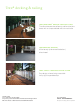
Trex® decking & railing TREX TRANSCEND® DECKING & RAILING SYSTEM The ultimate expression of beauty and function joins forces with unsurpassed fade and stain resistance TREX ENHANCE® DECKING All the beauty (and none of the bother) of real wood TREX® SELECT™ DECKING & RAILING SYSTEM Easy design scheme brings accessible luxury right to your doorstep ON THE COVER decking: Transcend® in Spiced Rum railing: Trex® posts in Classic White and Transcend in Vintage Lantern with a Tree House cocktail rail and r
Installation Guide INSTALLATION GUIDE ® In your hands, you’re holding everything you need to begin building with Trex® decking and railing. This step-by-step guide will show you how to create a beautiful outdoor living space that fits perfectly into your or your client’s lifestyle. Trex has been proven in the field. After almost twenty years of unparalleled performance, it offers warm, natural beauty and inviting comfort that no other product can match.
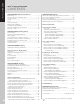
INSTALLATION GUIDE TREX® INSTALLATION GUIDE CONTENTS SECTION ONE: General Information General Tips.............................................................................5 Trex CustomCurve® (Bending Trex)......................................5 Job Site Storage......................................................................5 Safety.......................................................................................6 Tools........................................................................
GENERAL TIPS » Most colored chalk lines are permanent. Use baby powder or Irwin Strait-.Line®* Dust-Off Marking Chalk available at Irwin.com » We DO NOT recommend sanding. Sanding will change the appearance of the surface of Trex® material and will void the warranty with respect to any condition caused by such sanding. » When drilling large or deep holes, periodically lift the bit out of the hole to remove the shavings. » Throughout this guide, feet are converted to meters and inches to centimeters.
GENERAL INFORMATION SAFETY When working on any construction project, you should wear protective clothing and safety equipment. Wear safety glasses, gloves, a dust mask and long sleeves, particularly when cutting in confined spaces. Trex decking and railing are heavier and more flexible than wood. DO NOT try to lift the same quantity of Trex boards as you would traditional lumber. Go to Trex.com for Material Safety Data Sheets (MSDS).
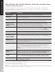
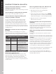
GENERAL INFORMATION TREX TRANSCEND®/TREX ENHANCE®/ TREX® SELECT™ CARE AND CLEANING GUIDE All exterior building materials require cleaning. Generally, soap and water is all that is required to clean Transcend, Enhance, and Select products. For further information, see below. PROBLEM SOLUTION Dirt and Debris The affected area should be sprayed off with a hose to remove surface debris. Use warm soapy water and a soft bristle brush to remove dirt and debris from the embossing pattern.
GENERAL INFORMATION TREX DECKING AND RAILING GENERAL CARE AND CLEANING GUIDE (STANDARD COMPOSITE AND PVC) All exterior building materials require cleaning. Trex recommends periodic cleaning with soap and water (for general dirt and debris) or a commercially available deck cleaner twice a year (for stains or mold/mildew). For additional information, see below. PROBLEM SOLUTION Dirt and Debris Clean deck to remove dirt and debris. Soap and hot water is all that is needed.
GENERAL INFORMATION MOLD TECHNICAL BULLETIN Mold is a lower form of plant life that can settle and grow on any surface, including Trex® decking. Mildew is a form of mold that grows on damp surfaces. Mold spores, transported by air, insects, animals, and water, are similar to seeds, but you can’t see them until colonies form. Because mold adapts easily to its environments and has a large number of species, it is hard to control and impossible to eliminate totally.
GENERAL INFORMATION PAINTING TECHNICAL BULLETIN Can Trex Transcend®, Enhance®, or Select™ decking be painted or stained? Trex Transcend, Enhance, and Select decking cannot be painted or stained.** Can Trex Escapes® can be painted or stained? Trex Escapes cannot be painted or stained.** Can Trex Accents® composite decking and railing be painted or stained? Yes, you can stain Trex Accents decking or railing to achieve a custom color, but it is not necessary for protection.
Through extensive testing, Trex has found a product to restore the color on PVC decking including Trex Escapes. The product is called DeckMax******. It is made from a patent pending plant-based solution that cleans and conditions the deck. It is easy to apply by using a microfiber mop. Depending upon the region that the deck is in, it should last on the deck from 1-2 years. It is available from the manufacturer at; www.deckmax.com or 888-219-9411.
CAL PROPERTIES GENERAL INFORMATION PHYSICAL AND MECHANICAL PROPERTIES FOR TREX TRANSCEND® AND TREX ENHANCE® Flame Spread (a) VALUES ASTM E84 100 Typical Trex Values for Coefficient of Thermal Expansion/Contraction (36" (91.4 cm) long samples) ® Thermal MECH Moisture PHYSICAL TEST METHOD Width 35.2 x 10⁻⁶ to 42.7 x 10⁻⁶ (inch/inch/°F) 644 x 10-6 to 776 x 10-6 (length/length/°C) Length 16.1 x 10⁻⁶ to 19.
CAL PROPERTIES MECH PHYSICAL TEST METHOD VALUES Abrasion Resistance ASTM D2394 .01 wear/1000 revs. Hardness ASTM D143 562 kg (5 kn) Self-Ignition Temperature ASTM D1929 743°F (395°C) Flash-Ignition Temperature ASTM D1929 698°F (370°C) Flame Spread (a) [Fire Defense] ASTM E84 80 [40] Water Absorption (sanded surface) 24 hr. immersion ASTM D1037 4.3% Water Absorption (unsanded surface) 24 hr. immersion ASTM D1037 1.
GENERAL INFORMATION GLOSSARY OF TERMS Standard Composite Trex Accents® PVC Trex Escapes® High Performance Composite Trex Transcend®, Trex Enhance®, Trex® Select™ Baluster One of a number of closely spaced supports for a railing. Baluster Spacer A piece that snaps into top and bottom rail that gives precise spacing to the balusters. Bird’s Mouth Gasket A 45° corner cut gasket to be used when attaching railing to the corner of a 4" x 4" (10.2 cm x 10.2 cm) post sleeve.
Steps or stairway boards that are the steps. Start Clip Metal clips used at the end of decking boards to secure them in position. Stringer The structural member in a stairway that supports the treads and risers. Tempered Glass A safety glass that is four to five times stronger than standard glass made by a process of extreme heating and cooling. Toenailing Attaching two pieces of decking together by driving a nail at an angle through one piece into the other. Universal Fastener Plastic 1/4" (0.
PLANNING AHEAD 16 PLANNING AHEAD
PLANNING AHEAD Trex® Decking: » When installing Trex Transcend® Tropical Colors of Spiced Rum, Lava Rock, and Tiki Torch, it is a good idea to mix and match all of the boards on the job site prior to installation to ensure an appealing mix of light and dark tones. Railing (Including ADA Handrail): » First, pick the railing style you want. » Determine the number of balusters you will need based on the railing you choose. See page 50. See www.trex.
PLANNING AHEAD/CONTINUED PLANNING AHEAD DeckProtect® padding/rack be moved from time to time for general cleaning underneath. It should be noted that even when using DeckProtect®, burning embers could “shoot” beyond the protective mat and burn the deck. Trex Pergola products are manufactured and sold by Home & Leisure, Inc., d/b/a Backyard America under a trademark license with Trex Company, Inc. For more information about this product, please visit their website at www.deckprotect.
NOTES PLANNING AHEAD 19
LIGHTING LIGHTING 20
TREX® DECKLIGHTING™ SPECIFICATIONS AND PROFILES LIGHTING DESCRIPTION Pyramid Post Cap Light » 4" x 4" (10.2 cm x 10.2 cm) LED Post Cap Light XXPYLEDCAP4X4 » 2 Gel-filled Wire Nuts BK, WT, FP, TH, VL, GP, RS Flat Post Cap Light » 4" x 4" (10.2 cm x 10.2 cm) LED Post Cap Light XXSQLEDCAP4X4 » 2 Gel-filled Wire Nuts BK, WT, FP, TH, VL, GP, RS Deck Rail Light » LED Deck Rail Light, 2.75" (6.99 cm) OD » 2 Gel-filled Wire Nuts BK, WT, BZ LED Riser 4-Pack » 4 LED Riser Lights, 1.25" (3.
HOW TO INSTALL TREX® DECKLIGHTING™ PARTS HELPFUL TIPS A A » Leave slack in wire to make fixture terminations. x2 Pyramid Post Cap Light B Flat Post Cap Light C x2 » Recessed lights work well spaced 4' (1.22 m) to 6' (1.83 m) on .center around parameter of deck. x2 x2 Deck Rail Light » Deck rail lights work well at changes in levels of a deck—at the top or the bottom of the stairs, or in place of post cap lights.
HOW TO INSTALL TREX® DECKLIGHTING™/CONTINUED General Information » ALWAYS consult local codes before beginning a project. » Straight runs over 100' (30.5 m) may require larger wire such as 16 or 14 gauge. » USE TREX TRANSFORMER ONLY. Use of any other transformer voids warranty. 2 TRANSFORMER CAPACITY BY TYPE 5A Transformer (DL TRANSFORMER) 2.5A Transformer (2.5 DL TRANSFORMER) Riser Light 240 120 Recessed Light 120 60 Post Cap 60 30 Deck Rail Light 240 120 Type of Light 2.
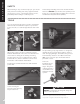
HOW TO INSTALL TREX® DECKLIGHTING™/CONTINUED 2. Place stripped wires together with insulation even. Twist connector onto wires pushing firmly until hand-tight. DO NOT over torque. Wipe sealant in and around conductors and connector opening while tightening. DO NOT reuse. 3 2 2 6" (15.2 cm) 1 1 2 Timer Operation Instructions 1. Select the mode of operation: » Dusk to Dawn » 1 - 8 hours » Always “ON” » “OFF” Program repeats daily. When power is flowing to lights, green light above POWER is on.
HOW TO INSTALL TREX® DECKLIGHTING™/CONTINUED Installing Riser Lights (continued) 2 3 NOTE: DO NOT install Riser Light or Deck Rail Light into top or bottom rails or balusters. Installing Recessed Deck Lights 3 2 4 3. Thread wires through hole. DO NOT pull LED into hole by pulling on wires. This may damage wires or LED. 4. Press light into hole until flush with surface. Make connections under deck with provided wire nuts. See Making Connections on page 23. LIGHTING 2. Drill a 1" (2.
DECKING DECKING 26
DECKING SPECIFICATIONS AND PROFILES DECKING DESCRIPTION 1" x 6" (2.5 cm x 15.2 cm) Square Edge Board 12' (3.66 m) 16' (4.88 m) 20' (6.1 m) Actual Dimensions: 1" x 5.5" (2.5 cm x 14 cm) Select Decking Actual Dimensions: .875 x 5.5" (2.2 cm x 14 cm) 1" x 6" Grooved-Edge Board Actual Dimensions: 1" x 5.5" (2.5 x 14 cm) 1" x 4.5" Grooved Porch Floor Board Actual face dimensions: 1" x 4.25" (2.5 cm x 10.8 cm) Actual Dimensions: 1" x 4.5" (2.5 cm x 11.
DECKING SPECIFICATIONS AND PROFILES TREX HIDEAWAY® HIDDEN FASTENING SYSTEM DESCRIPTION Connector Clip (stainless steel) Gun Pail 50 sq. ft. box 500 sq. ft. bucket 500 sq. ft. (46.5 m2) bucket with collated pneumatic screws CONNECTCLIP CLIPPAIL GUNCLIP Start Clip (stainless steel) Elevations Start Clip (stainless steel) 400 sq. ft. bag 400 sq. ft.
DECKING FASTENERS TREX® PRODUCT LINES Transcend® Enhance® Select™ Accents® Escapes® Trex Hideaway® Hidden Fastener X X X X X FastenMaster® TrapEase II Composite Screw X X X X Quick Drive® Composi-Lok Deck Screw X UFO Ballistic NailScrews® X Dexxter® Composite Screw – 6 Lobe Drive Only X X X X Fastenmaster® TrimTop Screw X Scrudini™ lHand Drive Screws X Camo® Marksman Pro® X DeckFast® Cap-Tor® xd /HeadCote® CapTor® xd X X X X X X
DECKING FASTENERS FASTENING TIPS FOR TREX ESCAPES®* TREX AND STATIC ELECTRICITY You can fasten Trex Escapes® with the above fasteners at least 1/2" (1.25 cm) and not more than 4" (10.2 cm) from the board edge without splitting. You do not have to pre-drill with Trex Escapes. The buildup of static electricity on a flat surface can affect walking surfaces. This phenomenon can occur in dry climates, where hot dry winds and dust-born particles can create static electricity on the surface of the decking.
FRAMING AND FASTENING TIPS Composite decking is a great alternative to traditional wood decking. When building your deck and railing, it is recommended that code-approved structural material be used as the framing and joists. One option is using Trex Elevations® steel deck framing. Refer to www.trex.com for more information on Trex Elevations . Check your local building codes for restrictions. Trex® decking cannot be used for structural applications.
ROOFTOP AND SLEEPER DECK SYSTEMS DECKING Sleeper Deck Systems A sleeper system is a buffer between a solid surface and Trex® decking. Drainage, access, and airflow are critical. Water must be able to flow through and away from the deck. For repairs and removal of debris, joist system access is necessary. Good airflow will keep the decking dry and in good condition.
CODE COMPLIANCE Joist Spanning for Decking Trex® decking meets all applicable national model building codes. The joists must be spaced on center according to the chart below. Be sure that joists are level and plumb. Trex decking must span at least three joists. For heavy items such as hot tubs, planters, etc., consult a local building engineer or inspector for span recommendations. If you want to minimize the appearance of joists through the spaces between boards, paint the top of your joists black.
GAPPING You must gap Trex® decking, both end-to-end and width-to-width. Gapping is necessary for drainage and the slight thermal expansion and contraction of Trex decking boards. Gapping also allows for the shrinkage of the wood joist system. 1/4" – 3/8" (0.6 cm – 1 cm) » ALWAYS follow Trex-recommended gapping guidelines. » Maximum allowable perpendicular overhang for Trex is 4" (10.2 cm). » All decks require air circulation to keep them dry and looking good. To improve air flow, leave .
STAIRS Stairway Detail MAXIMUM SPACING ON CENTER OF JOIST » Stair treads built with Trex meet requirements by the major national building codes. Consult your local municipality for specific requirements. ® » Fasten stair treads continuously across at least four stringers. 2" x 6" (5.1 x 15.2 cm), 1" (2.5 cm) Boards 12" (30.5 cm) Escapes 9" (24 cm) NOTE: For Trex® Select™ Stair Spans refer to www.trex.com » See chart (at right) for center-to-center spacing of profiles. 11" (27.9 cm) min.
TIPS FOR INSTALLING A TREX HIDEAWAY® HIDDEN FASTENING SYSTEM Installing Angled Deck Boards in Corners D G AR BO IN CK DE Shift 1/2" (1.3 cm) For Universal and Stainless Steel (Universal shown here) Routing Square Edge Boards for Trex Hideaway Fasteners NOTE: The following Trex Square Edge decking boards (Trex Transcend®, Trex Enhance®, Trex Escapes®, Trex Accents®), either 1x6 or 2x6, can be routed. For Trex Select™ decking, refer to www.trex.com for more details.
HOW TO INSTALL TREX HIDEAWAY® STAINLESS STEEL FASTENERS (TREX TRANSCEND®, ENHANCE®, ACCENTS®) NOTE: Cannot be used for Trex Escapes®. Installing Second Board PARTS Bump stop tab Start clip 5 Connector clip TOOLS NEEDED 1/4" (0.6 cm) NOTE: Maximum spacing of deck boards using the Hideaway system is 16" (40.6 cm) on center. Fasteners provide 1/4" (0.6 cm) gap when installed correctly. Installing Start Clips and First Board 2 1 5. With next deck board in position and 2" (5.
HOW TO INSTALL TREX HIDEAWAY® UNIVERSAL HIDDEN FASTENERS (TREX TRANSCEND®, ENHANCE®, ESCAPES®, ACCENTS®) NOTE: See page 39 for additional instructions if installing Escapes. Installing Second Board PARTS 5 Start clip Universal fastener TOOLS NEEDED 1/4" (0.6 cm) NOTE: Maximum spacing of deck boards using Hideaway system is 16" (40.6 cm) on center. Fasteners provide 1/4" (0.6 cm) gap when installed correctly. Installing Start Clips and First Board HOW TO INSTALL DECKING 1 1.
HOW TO INSTALL ESCAPES® BOARDS WITH TREX HIDEAWAY® UNIVERSAL FASTENERS 1. Follow steps 1 and 2 for installing start clips and first board. See page 38. 2. At both ends and center of first board, toenail screw (provided with Escapes universal hidden fasteners), at an angle through grooved edge of deck board. 3. Follow steps 3-5 for installing universal fasteners. See page 38. 4. For every consecutive board installed, toenail screw at an angle through grooved edge of deckboard as stated in Step 2. 5.
HOW TO REPLACE TREX® BOARDS/CONTINUED INSTALLED WITH TREX HIDEAWAY® UNIVERSAL FASTENERS (TREX TRANSCEND®, ENHANCE®, ESCAPES®, AND ACCENTS®) Universal Fasteners Insert Fasteners 3 3. Slide a fastener for each joist into board grooves from both ends of the board. Insert Fasteners NOTE: You may have to loosen .adjacent boards to slide fasteners into position. 4. Position replacement board and secure fasteners on center of each joist.
HOW TO INSTALL TREX TRANSCEND® PORCH FLOORBOARDS NOTE: When installing Trex Porch Floorboards in a non-covered environment, the porch structure should be slightly sloped to help allow for proper drainage. Joists should be sloped 1/8" (0.3 cm) per foot away from the house to facilitate drainage. Refer to your local building code official for recommendations BEFORE building sub-structure. When installing Trex Porch Floorboards under cover of a roof, no slope is required.
HOW TO INSTALL TREX TRANSCEND® PORCH FLOORBOARDS/CONTINUED Installing Last Porch Floorboard Option 1: Using Fascia Board 7a. Pre-drill pilot holes at an angle through grooved edge of porch floorboard into ledger board. Install 2-1/2" (6.4 cm) screws through pilot holes to secure. Attach fascia board flush with porch floorboard surface. Option 2: 7a 1 2 NOTE: In most cases there will be additional screws that come with the Trex Hideaway® Universal Hidden Fasteners.
HOW TO INSTALL 4X4 AND 5X5 STRUCTURAL PORCH POSTS PARTS » » » » » » Aluminum support tube Decorative column Filler strips Mounting plate(s) Post skirts (not provided) #10 x 1.000" screws Measuring and Cutting Aluminum Support Tube 1 1/2" (1.3 cm) 1. Measure opening height and cut aluminum support tube 1/2" (1.3 cm) shorter. Attaching Support Tube to Mounting Plate 2 TOOLS NEEDED 2 2. Insert support tube into center of mounting plate between outside tabs.
HOW TO INSTALL 4X4 AND 5X5 STRUCTURAL PORCH POSTS/CONTINUED Attaching Decorative Column to Mounting Plate 4 4. Slide the decorative column over the support tube leaving about 24" (61 cm) exposed. 24" (61 cm) 9. Slide two post skirts (not provided) onto top and bottom of decorative column and place entire assembly into opening in desired location. 9 NOTE: DO NOT slide decorative column on rough surfaces to avoid scratching.
HOW TO INSTALL POST MOUNTS ON DECK BOARD NOTE: Cannot be used with Trex Transcend® Classic railing or Trex Traditional railing styles. NOTE: If using Trex 48" Newel Post, a post mount system must be used. Position Leveling Plate 2 PARTS » » » » » » » » » » » (1) Post mount (2) Guide blocks (4) 5/16" x 6" (0.8 cm x 15.2 cm) Hex (mounting) bolts (4) 5/16" x 1" (0.8 cm x 2.5 cm) Hex (leveling) bolts (1) Leveling plate (1) Back plate (8) Flat washers (4) Hex nuts (4) 3/4" (1.
HOW TO INSTALL POST MOUNTS ON DECK BOARDS/CONTINUED Install Railing System of Choice 4b Inline NOTES: If installing a Trex® railing system: » Mark screw placement on post sleeve for the rail support brackets (RSBs). » Pre-drill screw holes through post sleeve and aluminum guide blocks with a 1/8" (0.3 cm) drill bit. Offset 4b. Use center holes for inline applications and offset holes for corner applications. Install Guide Blocks HOW TO INSTALL DECKING 5 » Attach RSBs using 2" (5.
HOW TO INSTALL POST MOUNTS ON CONCRETE/CONTINUED Install Mounting Bolts TOOLS NEEDED 3 Position Leveling Plates 1 3. Secure post mount with four concrete bolts and washers. NOTE: Torque recommended is 5 - 10 ft. lbs. Install Guide Blocks 1/4" (0.6 cm) 1. 4 Install Leveling Bolts and Level Post Mount 2a 2b x4 4. Place the two guide blocks on post mount and secure with self-tapping screws (provided). Install Railing System of Choice 2a. Partially thread four 5/16" x 1" (0.8 cm x 2.
HOW TO INSTALL POST MOUNT UPPER ALUMINUM GUIDE BLOCK WITH TREX NEWEL POST FOR RAILING ASSEMBLY TOOLS NEEDED 4 Post Sleeve Aluminum Guide Block RSB NOTE: When using the post mount system with the Trex Newel Posts for railing, the method of attachment for the upper aluminum guide block cannot be attached as per the instructions. 1. Install post mounts as per previous instructions. See pages 45 - 47. 2. Install lower guide block as per previous instructions. See pages 46 - 47. 4.
RAILING RAILING 49
TREX TRANSCEND® RAILING SPECIFICATIONS AND PROFILES PART DESCRIPTION ITEM NUMBER COLORS Post Sleeve/Porch Post/ Newel Post 4" x 4" x 39" (10.2 cm x 10.2 cm x 99.1 cm) Post Sleeve 4" x 4" x 108" (10.2 cm x 10.2 cm x 2.74 m) Post Sleeve XX040439APS XX0404108APS WT, BK, TH, VL, GP, FP, RS WT060639APS WT0606108APS WT WT (Each 4" x 4" (10.2 cm x 10.2 cm) post sleeve includes a corrugated TrexExpress™ Railing Assembly Tool.) (Actual dimensions of 4x4 Post Sleeve is 4.45" x 4.45") 6" x 6" x 39" (15.
TREX TRANSCEND® RAILING SYSTEMS RAILING SYSTEM DESCRIPTION ITEM NUMBER Accessory Infill Kit 6' (1.83 m) Accessory Infill Kit for Square/ Colonial Balusters—Horizontal XXSQHIK06 WT, BK, TH, VL, GP, FP, RS 6' (1.83 m) Accessory Infill Kit for Square/ Colonial Balusters— Stair XXSQSIK06 WT, BK, TH, VL, GP, FP, RS 8' (2.43 m) Accessory Infill Kit for Square/ Colonial Balusters—Horizontal XXSQHIK08 WT, BK, TH, VL, GP, FP, RS 8' (2.
TREX® SELECT™ RAILING RAILING SYSTEM DESCRIPTION ITEM NUMBER Rail and Baluster Kit 6' x 36" Rail & Baluster Kit—Horizontal 6' x 36" Rail & Baluster Kit—Stair WT0636HSELK WT0636SS ELK 8' x 36" Rail & Baluster Kit—Horizontal 8' x 36" Rail & Baluster Kit—Stair WT0836HSELK WT0836SS ELK Select Accessories Mounting Hardware for Cut Rails—Horizontal (10 kits/box) Mounting Hardware for Cut Rails—Stair (10 kits/box) 45 Degree Adapter Kit (10 kits/box) WTHSELCUT WTSS ELCUT WTSEL45ADP WT Bulk Packs 6' Top
DESIGNER/TRADITIONAL RAILING SPECIFICATIONS AND PROFILES PART DESCRIPTION ITEM NUMBER Posts 4" x 4" x 48" (10.2 cm x 10.2 cm x 121.9 cm) Post Sleeve 4" x 4" x 108" (10.2 cm x 10.2 cm x 274.3 cm) Post Sleeve XX040448PS XX0404108PS SD, WB, WG, MB 4" x 4" (10.2 cm x 10.2 cm) Post Sleeve Skirt XXRPSSKIRT SD, WB, WG, MB ' (1.83 m) Top and Bottom Rail Kit* 6 *Includes standard top and bottom rails, baluster for foot block, and mounting hardware. XX06HRK (Level and stair sections available.
ADA RAILING SPECIFICATIONS AND PROFILES DESCRIPTION ITEM NUMBER 1 104" (264.2 cm) Straight rail BKADARAIL 1.5" (3.8) diameter (PVC with aluminum stiffener) 2 Wall Return with Cover Plate COLORS Black 2 1 BKADA90WRK Black (PVC with aluminum stiffener) 3 5 4 3 Straight Wall Return BKADASWRK 10 Black 7 4 Handrail Bracket with Screws and Cap BKADARBK 11 Black 6 5 90° Corner BK90CORN Black NOTE: No. 8 straight joiner and No. 9 adjustable joiner are not visible.
TREX TRANSCEND® RAILING NOTE: All Trex Transcend Railing lengths are manufactured at ON CENTER dimensions (spanning from center of each post): 67-5/8" (171.8 cm) for 6' (1.83 m) on center, and 92-5/8" (235.3 cm) for 8' (2.44 m) on center. Note that railings are designed to be slightly longer that required to allow for very slight play in post placement – some minimal trimming may be required. IT IS VERY IMPORTANT TO MEASURE FIRST.
TREX TRANSCEND® DECK RAILING Standard Crown or Beveled Cutting post sleeves is NOT required. A. Pressure-treated post or Trex post mounts with Trex Transcend post sleeve B. Crown or Beveled rail C. Universal bottom or Beveled rail D. Trex balusters See page 57 for “How to Install Standard Crown or Beveled Railing”. B A D C Classic B C A E D Colonial B C A E D Round Aluminum POST Post sleeves WILL NEED TO BE CUT. SLEEVES A.
HOW TO INSTALL STANDARD CROWN OR BEVELED RAILING TREX TRANSCEND® Installing Railing Support Brackets (RSBs) Option 1: Without TrexExpress™ Railing Template 3b 3a 1 2 3 4 35-1/16\ 35-1/16" (89.1 cm) or 41-1/16\ 41-1/16" (104.3 cm) 5-1/2" (14 cm) Read all instructions BEFORE installation. Important: Post sleeves are NOT to be cut for this design style. Installing PressureTreated Posts 1 » Posts are to be installed 2" x 8" (5.1 cm x 6' (1.83 m) or 8' 1" (2.5 cm) min. 20.3 cm) min. (2.
HOW TO INSTALL STANDARD CROWN OR BEVELED RAILING/CONTINUED TREX TRANSCEND® Cutting Railings 4. Measure between posts and cut rails to same length. 4a 5c. Telescope foot block down and screw through opposite sides. Place screw plugs. 5c 1 2 NOTES: » If using optional rail gaskets, subtract 1/16" (0.15 cm) from each end. 3 2 » Attach baluster spacers to railing before cutting to allow for cleaner cut and less work.
HOW TO INSTALL STANDARD CROWN OR BEVELED RAILING/CONTINUED TREX TRANSCEND® Attaching Top Rail – Crown or Beveled Rail 8 Option 9 2 1 Attaching Post Caps 10. S ecure post caps with silicone or PVC adhesive. 10 2 NOTE: Clean-up any excess adhesive before drying. 2 1 x2 3 2 8. Place Crown or Beveled rail on RSBs with balusters in rail channels. Attach top rail to RSB with two selftapping screws (provided). 9. Slide baluster spacer up and snap into top rail.
HOW TO INSTALL CLASSIC RAILING/CONTINUED TREX TRANSCEND® Attaching the Inverted Universal Rail as Top Rail 8 10 11 9 1 1 1 3 2 2 8. Place inverted Universal rail onto RSBs with balusters in channel. Attach Universal rail to RSBs with two self-tapping screws (provided). 9. Place deck boards (DO NOT use Escapes, Select, or Contour deck boards for top rail) over Universal rails. Attach boards on each post with Trexrecommended composite screws at a diagonal.
HOW TO INSTALL COLONIAL RAILING/CONTINUED TREX TRANSCEND® Attaching Inverted Universal Rail as Top Rail 8 9 11 Optional 2 1 1 x2 11. Slide baluster spacer up and snap into Universal rail. 2 8. Place inverted Universal rail onto RSBs with balusters in channel. Attach Universal rail with two self-tapping screws (provided). 9. Measure between posts and cut 2" x 4" (5.1 cm x 10.2 cm) to length. 10. Place 2" x 4" (5.1 cm x 10.2 cm) on Universal rail. Attach board to rail with 2" (5.
HOW TO INSTALL STANDARD GLASS PANEL CROWN OR BEVELED RAILING/CONTINUED TREX TRANSCEND® 9. Push PSM into rail to complete snap connection. Lower rail PSM edge rests on top of rail. Top rail PSM snaps flush into rail. If using Beveled rails, the PSM will rest on the edges on the rail. 1. Installing Pressure-Treated Posts See instructions on page 57. 2. I nstalling Post Sleeve Skirts and Post Sleeves See instructions on page 57. Hiding Brackets 3.
HOW TO ATTACH CLASSIC STYLE GLASS PANEL RAILING TREX TRANSCEND® 3. I nstalling Railing Support Brackets (RSBs) See instructions on page 57. 4. C utting Railings See instructions on page 58. 5. Attaching Bottom Rail (Universal or Beveled rail) and Foot Block See instructions on page 58. Attach Weatherstripping and Positioning Panel NOTES: Read all instructions BEFORE installation. 6 7 63-1/2" (161.3 cm) » You must purchase the 1/4" (0.6 cm) tempered glass panels. See dimensions below.
HOW TO ATTACH CLASSIC STYLE GLASS PANEL RAILING/CONTINUED TREX TRANSCEND® 9 10 14. Install four panel support moldings (PSM) into rails to complete snap connection. Both the top and bottom PSM edges rest on the lip of the rails for both Universal and Beveled rails. 9. Place inverted deck board (place top side of deck board down) on clean, flat surface. (DO NOT use Escapes, Select, or Contour deck boards for top rail. 10.
HOW TO ATTACH COLONIAL STYLE GLASS PANEL RAILING TREX TRANSCEND® Attach Weatherstripping and Positioning Panel 6 7 63-1/2" (161.3 cm) 2" (5.1 cm) NOTES: Read all instructions BEFORE installation. » You must purchase the 1/4" (0.6 cm) tempered glass panels. See dimensions below. » Glass panels ONLY for use with maximum 6' (1.83 m) on center post spacing. » NOT recommended for stair applications. 6. Push black-edged trim onto upper and lower edges of panel.
HOW TO ATTACH COLONIAL STYLE GLASS PANEL RAILING/CONTINUED TREX TRANSCEND® 9 10 14. Install four panel support moldings (PSM) into rails to complete snap connection. Both the top and bottom PSM edges rest on the lip of the rails for both Universal and Beveled rails. 9. Place inverted 2" x 4" (5.1 cm x 10.2 cm) (place top side down) on clean, flat surface. 10.
HOW TO INSTALL ON-AN-ANGLE RAILING TREX TRANSCEND® (CROWN AND UNIVERSAL RAILING) NOTE: Trex Railing brackets are designed to be installed up to a 45° angle. 4x4 6x6 » Small angles (1° - 30°). Both 4" x 4" (10.2 cm x 10.2 cm) or 6" x 6" (15.2 cm x 15.2 cm) post sleeves work well. » Large angles (31° - 45°). USE ONLY 6" x 6" (15.2 cm x 15.2 cm) post sleeves when installing on flat side. » 45° angles using 4" x 4" (10.2 cm x 10.2 cm) post sleeves MUST use Transcend bird’s mouth brackets.
HOW TO INSTALL CROWN, UNIVERSAL, AND BEVELED BIRD'S MOUTH RAILING Attaching Adapters TREX TRANSCEND® Snap adapters into RSBs. NOTES: » Use with 4" x 4" (10.2 cm x 10.2 cm) post sleeve ONLY. » Gaskets are only designed for use with Transcend Crown and Universal railing (not Beveled railing). Pre-drill Bottom and Top RSBs 2 3 Read all instructions BEFORE installation. PARTS 2. Position RSBs with adapter (flat side DOWN) for lower rail, mark and pre-drill screw holes with 1/8" (0.
HOW TO INSTALL CROWN, UNIVERSAL, AND BEVELED STAIR RAILING TREX TRANSCEND® Read all instructions BEFORE installation. NOTE: All Transcend railings and gaskets work ONLY WITH STAIR SLOPES OF 32°-37°. Installing Posts, Post Sleeve Skirts, and Post Sleeves for Stair Rails Positioning RSBs on BOTTOM Post 3 2 1 1. Install posts, post sleeve skirts, and post sleeves according to standard Transcend railing instructions. See page 57. » In most cases, a post and post sleeve longer than 39" (99.
HOW TO INSTALL CROWN, UNIVERSAL, AND BEVELED STAIR RAILING/CONTINUED TREX TRANSCEND® Complete Stair Rails Installation Positioning RSBs on UPPER Post 5 7. Install foot blocks prior to installing lower rail. Refer to “How to Install Universal and Beveled Railing Foot Blocks” on page 71. For stair application, cut top section of foot block at an angle to match rail, pre-drill, and fasten. 2 1 3 7 5. Position pre-cut bottom rail between posts.
HOW TO INSTALL UNIVERSAL AND BEVELED RAILING FOOT BLOCKS TREX TRANSCEND® Read all instructions BEFORE installation. Drill Pilot Hole for Foot Block Base Plate 2 IMPORTANT NOTES: » BEVELED RAILING NOTES: • I F YOU HAVE A FOOTBLOCK WITH A DATE CODE OF ART-FTB-1108 ON THE INSTRUCTION SHEET (LOCATED ON BOTTOM RIGHT CORNER OF INSTRUCTIONS), THE FOOTBLOCK WILL NEED TO BE TRIMMED PRIOR TO ATTACHMENT TO BOTTOM RAIL. SEE STEPS 1A - 1C FOR DETAILS.
HOW TO INSTALL UNIVERSAL AND BEVELED RAILING FOOT BLOCKS/CONTINUED TREX TRANSCEND® Attaching Foot Block to Bottom Rail HOW TO INSTALL CROWN, UNIVERSAL, AND BEVELED FOOT BLOCK FOR STAIR RAILING TREX TRANSCEND® 4 1 2 4. Center foot block in Universal rail channel or on underside of Beveled rail at center and attach collapsed foot block (DO NOT extend foot block) to rail using 2" (5.1 cm) screw (provided). Cutting Foot Block 7a 7b 7c 7a.
TREX® SELECT™ RAILING NOTE: All Trex Select Railing lengths are manufactured at ON CENTER dimensions (spanning from center of each post): 67-5/8" (176.8 cm) for 6' (1.83 m) on center, and 92-5/8" (235.3 cm) for 8' (2.44 m) on center. Note that railings are designed to be slightly longer that required to allow for very slight play in post placement – trimming may be required. IT IS VERY IMPORTANT TO MEASURE FIRST.
HOW TO INSTALL TREX® SELECT™ RAILING TREX SELECT™ Cutting Railings 3 Attaching Foot Block to Bottom Railing 4 3. Measure between posts and cut rails to same length. When measuring, cut equal lengths from each side of railing allowing a minimum of 1-5/16" (3.3 cm) on each end. This will ensure proper baluster and bracket placement and equal spacing of balusters per each railing section. To allow for bracket attachment on each end of the railing, cut an additional 1/4" (0.6 cm) max.
HOW TO INSTALL TREX® SELECT™ RAILING/CONTINUED TREX SELECT™ 5c 5d 5c. Attach top rail to balusters, feeding each baluster into required slots. Start on one end and work towards the other. 5d. To help temporarily secure the railing section together, place a ratchet strap around the top and bottom rail and tighten until snug. DO NOT OVERTIGHTEN AS YOU CAN BEND THE RAILING. 6d 6e 6d. Install bottom bracket (both sides) to post using four #8-10 x 2" (5.1 cm) screws per bracket (provided). 6e.
HOW TO INSTALL TREX® SELECT™ STAIR RAILING TREX SELECT™ Read all instructions BEFORE installation. NOTE: All Select railings work ONLY WITH STAIR SLOPES OF 32°-37°. Installing Posts, Post Sleeve Skirts, and Post Sleeves for Stair Rails 1 1. Install posts, post sleeve skirts, and post sleeves according to standard Select railing instructions. Cutting Balusters on Angle (OPTIONAL) 3a 3a.
HOW TO INSTALL TREX® SELECT™ STAIR RAILING/CONTINUED TREX SELECT™ Attaching Footblock to Bottom Railing 5b » REFER TO PAGE 80 FOR DETAILED INSTRUCTIONS ON INSTALLATION OF FOOT BLOCK (BASIC STEPS ARE SHOWN BELOW). 4a 4b 1 2 4a. F or stair applications, cut the section of foot block at an angle to match rail. Refer to foot block instructions for specific information on how to do this. 4b. Invert bottom rail. Center foot block on bottom rail and attach. DO NOT extend foot block.
HOW TO INSTALL TREX® SELECT™ STAIR RAILING/CONTINUED TREX SELECT™ Attachment of Top Rail to Post Attaching Bracket Covers and Post Caps 7a 9a 7a. Slide top stair brackets on top rail (tab on bracket should be facing up) on each side. 9a. Snap bracket covers over top rail bracket. 9b. Snap bracket covers over bottom rail bracket. 7b 7c 9c. Secure post caps with silicone or PVC adhesive. NOTE: Clean-up any excess adhesive before drying. 7b.
HOW TO INSTALL TREX® SELECT™ RAILING FOOT BLOCKS TREX SELECT™ Drill Pilot Hole for Foot Block Base Plate Read all instructions BEFORE installation. 2 NOTE: Foot blocks must be placed before installing bottom rails. NOTE: One centered foot block is required for every section of railing or stairway section. Attaching Foot Block to Bottom Rail 1a 1 1 2. Center bottom railing with foot block attached (DO NOT EXTEND FOOT BLOCK) in between post span.
HOW TO INSTALL TREX® SELECT™ RAILING FOOT BLOCKS/CONTINUED TREX SELECT™ Extending and Securing Foot Block 5a 5b. W ith foot block fully seated on base plate, secure with two 3/4" (1.9 cm) retaining screws (provided). Install one on each side of foot block 1-1/2" (3.8 cm) from bottom of base. Push in screw plugs/ covers. 5b 1-1/2" (3.8 cm) 2 1 5a. Extend foot block to seat on foot block base plate.
TREX DESIGNER SERIES RAILING® Trex Designer Series Railing® Parts A. Top rail B. Bottom rail C. Railing support brackets (RSBs) D. Balusters* E. Post sleeve* F. Post sleeve cap* G. Post sleeve skirt* H. TrexExpress™ Designer Series Railing Assembly Tool* * Item not included in Designer Railing Kit NOTE: Architectural baluster cannot be used with Designer Series Railing. NOTE: Position of bottom rail lip is not a structural component.
HOW TO INSTALL STANDARD RAILING TREX DESIGNER SERIES Installing Railing Support Brackets (RSBs) Option 1: Without TrexExpress™ Designer Series Railing Assembly Tool 3b 3a 1 35-1/16\ 35-1/2" (90.2 (89.1 cm) cm) or 41-1/16\ 41-1/2" (105.4 cm) (104.3 4" (10.2 cm) 2 All Trex Designer Series Railing® uses the same application for attaching posts to the rim joists. Posts may be pressure-treated wood or a Trex Railpost™. Read all instructions BEFORE installation.
HOW TO INSTALL STANDARD RAILING/CONTINUED TREX DESIGNER SERIES Assembling Rails with Balusters Securing Balusters to Top Rail 5 7 1 1 1 1 1 2 5. Place bottom rails on their sides, lip sides facing up. Using TrexExpress™ Designer Series Railing Assembly Tool, set balusters in designated slots. NOTE: Using two assembly tools and overlapping these will allow you to span the entire length of the railing section for a 6' (1.83 m) span.
HOW TO INSTALL STANDARD RAILING/CONTINUED DESIGNER SERIES Securing Railings to Posts 9 1 Bottom Rail 2 1 x2 Top Rail 3 9. Place assembled railing section on RSBs on posts and secure top rail with two 1-1/2" (3.8 cm) screws. Secure bottom rail with screws through top of rail and into the outermost hole in RSBs. Bottom rail can also be secured to posts with 16 gauge finishing nails, toenailed from bottom of rail and 1" (2.5 cm) in from the posts. Finishing Post 10 2 1 DESIGNER RAILING 3 84 10.
HOW TO INSTALL CONTEMPORARY RAILING TREX DESIGNER SERIES Option 2: If using Designer Balusters for Foot Blocks 5b 18" (45.7 cm) 1. Installing Posts See instructions on page 82. 2. Installing Post Sleeve Skirts and Post Sleeves See instructions on page 82. 5b. Measure and cut square balusters for foot blocks every 18" (45.7 cm). Secure foot blocks with 2" (5.1 cm) 16 gauge finishing nails through side of bottom rail. 3. Installing Railing Support Brackets (RSBs) See instructions on page 82.
HOW TO INSTALL CONTEMPORARY RAILING/CONTINUED TREX DESIGNER SERIES DETERMINING NUMBER OF BALUSTERS AND SPACING Installing Top Rail 9 Number of balusters needed Length of rail ______" ÷ 4.5 = ______balusters » If number is odd, balusters will be centered. » If number is even, balusters will be offset 2-1/4" (5.7 cm) from center. Installing Baluster Connectors 1 7 2 1 9. Lower top rail with connectors between posts onto RSBs and then secure balusters on connectors.
HOW TO INSTALL STANDARD STAIR RAILING TREX DESIGNER SERIES NOTE: Trex rails meet major building codes for use as a guardrail system. Local municipalities may require a graspable handrail on stairways. Trex offers an ADA code-compliant handrail system. Check with your local building code officials for local requirements. Installing Posts for Stair Railing Installing Bottom RSBs on Upper and Lower Posts 3 1 1. In most cases, a railpost or post sleeve longer than 39" (99.
HOW TO INSTALL STANDARD STAIR RAILING/CONTINUED TREX DESIGNER SERIES Installing Top Rail RSBs on Upper and Lower Posts 6. Determine height of top rail from bottom rail and while holding top rail in place, and parallel to bottom rail, mark posts where underside of rail intersects. 7. Follow Steps 4-5 to install top rail RSBs on upper and lower posts. Securing Balusters to Top and Bottom Rail 10 Measuring and Cutting Balusters 8 2 2 10. Secure balusters to top rail with 2" (5.
HOW TO INSTALL STANDARD STAIR RAILING/CONTINUED TREX DESIGNER SERIES Mounting Rails on Posts 12 Bottom rail can also be secured to posts with 16 gauge finishing nails, toenailed through the side of rail into the posts, 1-1/2" (3.8 cm) from bottom of rail and 1" (2.5 cm) from the post. Finishing Posts 1 1 3 2 12. Place assembled railing section on RSBs on posts and secure top rail with two 1-1/2" (3.8 cm) screws. Secure bottom rail with screws through outermost holes in RSBs. 13.
HOW TO INSTALL CONTEMPORARY STAIR RAILING/CONTINUED TREX DESIGNER SERIES Installing Bottom Rail Connecting Balusters to Bottom Rail 9 11 1 1 2 9. Secure bottom rail with screws through top of rail and into the outermost hole in RSBs. Bottom rail can also be secured to posts with 16 gauge finishing nails, toenailed from bottom of rail and 1" (2.5 cm) in from the posts. 11. Lower each baluster down onto connectors on bottom rail.
TREX® TRADITIONAL RAILING Trex® Traditional Railing Parts List A. Top rail B. Lateral rail C. Balusters D. Post sleeve E. Post sleeve skirt F. Trex decking G. TrexTrim™ or Trex fascia H. Code-approved wood joist - 2" x 8" (5.1 cm x 20.3 cm) I. Code-approved wood rim joist - 2" x 8" (5.1 cm x 20.3 cm) or larger J. Foot block » Escapes and 5" (12.7 cm) Contours cannot be used for top rail. » 6 . " x 6" (15.2 cm x 15.2 cm) post sleeve cannot be used with any Trex Traditional railing installs.
TREX® TRADITIONAL RAILING Traditional Railing Styles With Standard Trex Designer Balusters/Option 1 A. Pressure-treated post with Trex Designer post sleeve or Trex Transcend® 4" x 4" (10.2 cm x 10.2 cm) post sleeve B. Deck board top rail NOTE: DO NOT USE with Escapes. C. 2" x 4" (5.1 cm x 10.2 cm) Lateral top and bottom rail D. Trex Designer balusters See page 93 for “How to Install Raised Railing/Option 1”. With Contemporary Balusters/Option 2 A.
HOW TO INSTALL RAISED RAILING TREX® TRADITIONAL/OPTION 1 Rails BETWEEN Posts with STANDARD Trex Balusters Cutting Posts to Length and Installing Top Rail 3 42" Max. (106.7 cm) 36" Min. (91.4 cm) 2 x2 Installing PressureTreated Posts » Attach posts using 1/2" (1.3 cm) carriage bolts. 3. Cut posts to designated height as measured from top of decking surface. Measure distance between posts from center-to-center. 1 2" x 8" (5.1 cm x 20.3 cm) min.
HOW TO INSTALL RAISED RAILING/CONTINUED TREX® TRADITIONAL/OPTION 1 5 Installing Balusters 1 2 1 1 6 3-5/8" (9.2 cm) 1 1 3 3-1/2" max. (8.9 cm) 1 2 5" (13 cm) 5. Center upper lateral rails under top rails to posts attaching with “L” brackets or equivalent construction method. (If toenailing screws into lateral railing, predrill these holes first to help prevent splitting and mushrooming of the screw.) Secure with 2-1/2" (6.
HOW TO INSTALL RAISED RAILING TREX® TRADITIONAL/OPTION 2 Rails BETWEEN Posts with CONTEMPORARY Balusters Installing Foot Blocks NOTE: This step is done BEFORE you attach the 2" x 4" (5.1 cm x 10.2 cm) bottom lateral rail to posts. 3 18" (45.7 cm) 1. Attaching Posts, Post Sleeve Skirts, and Post Sleeves See instructions on page 93. Cutting Posts and Lateral Rails to Length 3. Option 1: Cut round balusters for foot blocks and place every 18" (45.7 cm).
HOW TO INSTALL RAISED RAILING/CONTINUED TREX® TRADITIONAL/OPTION 2 Rails BALUSTER BETWEENSIZE Posts with CONTEMPORARY AND SPACING OPTIONS Balusters Securing Upper Lateral Rail 7 For 36" (91.4 cm) rail height, use Trex 26" (66 cm) 1. contemporary Attaching Posts, Post Sleeve Skirts, and balusters. Part number: BK3Q26RBK Post Sleeves See instructions on page 62 and 64. For 42" (106.7 cm) rail height, use Trex 32" (81.3 cm) Cutting Posts and Lateral to Length contemporary balusters.
HOW TO INSTALL RAISED STAIR RAILING TREX® TRADITIONAL/OPTION 2 Installing Stair Railing with Contemporary Balusters BALUSTER OPTIONS AND CONNECTORS Installing Foot Blocks NOTE: This step is done BEFORE you attach the 2" x 4" (5.1 cm x 10.2 cm) bottom lateral rail to posts. 3 For 36" (91.4 cm) rail height, use Trex 26" (66 cm) contemporary balusters. Part number: BK3Q26RBK For 42" (106.7 cm) rail height, use Trex 32" (81.3 cm) contemporary balusters. Part number: BK3Q32RBK 18" (45.7 cm) Black 3/4" (1.
HOW TO INSTALL RAISED STAIR RAILING/CONTINUED TREX® TRADITIONAL/OPTION 2 Securing Bottom Lateral Rail Installing Top Hand Rail 5 8 1 1 1 1 2 x2 5. Place bottom lateral rail between posts and attach using “L” brackets or equivalent construction method. Secure with 2-1/2" (6.4 cm) compositeapproved screws. Installing Balusters and Top Lateral Rail 6 6. Insert end of balusters into adapters on bottom rail. TRADITIONAL RAILING 7 98 1 2 2 7.
HOW TO INSTALL RAISED RAILING TREX® TRADITIONAL/OPTION 3 Rails BETWEEN Posts with ARCHITECTURAL Balusters Cutting Lateral Rail 3 1. Attaching Posts, Post Sleeve Skirts, and Post Sleeves See instructions on page 93. 1/16" (0.15 cm) Cutting Posts to Length and Installing Top Rail 2 1 1 42" Max. (106.7 cm) 36" Min. (91.4 cm) 3. Measure distance between inside edges of posts and cut two 2" x 4" (5.1 cm x 10.2 cm) lateral rails to fit. Leave 1/16" (0.15 cm) gap at each end for cold weather expansion.
HOW TO INSTALL RAISED RAILING/CONTINUED TREX® TRADITIONAL/OPTION 3 Attaching Lateral Rail with L-Brackets 5 Installing Balusters 6 1 25-1/4" (64.1 cm) 1 1 1 1 3-1/2" (8.9 cm) 2 2 3-1/2" max. (8.9 cm) 5. Center lateral rail under top rail and attach to posts using an “L” bracket or equivalent construction method. Secure with 2-1/2" (6.4 cm) composite-approved screws and attach top rail with one screw every 12" (30.5 cm). BALUSTER SIZE AND SPACING OPTIONS For 36" (91.
HOW TO INSTALL RAISED STAIR RAILING TREX® TRADITIONAL/OPTION 3 Installing Stair Railing with Architectural Balusters Installing Foot Blocks 3 BALUSTER OPTIONS AND CONNECTORS or 36" (91.5 cm) rail height, use Trex 32" (81.3 cm) F architectural balusters. Part number: BK0132VBK 18" (45.7 cm) For 42" (106.7 cm) rail height, use Trex 40" (101.6 cm) architectural balusters. Part number: BK0140VBK Measure baluster spacing Length of rail ______" ÷ 5.
TREX® ADA RAILING Stair Application ADA Handrail Guidelines 1. You can install ADA handrails using various design applications such as those for stairs, ramps, and horizontal inclines. Designs include options for straight and 90° wall returns, 90° corners, and adjustable angles. Choose which is best for your needs before installing. 2. The handrail system top rail should be 34" (86.4 cm) to 39" (99.1 cm) above the surface.
HOW TO INSTALL TREX® ADA RAILING 90° Wall Return Handrail Bracket 2 4 IVE ADHES METAL 4 2 2 1 3 5 1 4 3 Cut the aluminum and PVC tube to proper length. 1. Apply adhesive to all metal contact surfaces. 2. Make sure flange cover is placed over PVC rail prior to assembly. 3. Slide straight joiner into wall return and aluminum rail support. 4. Attach mounting flange to desired surface. Snap flange cover into place. NOTE: Hardware not included. Straight Wall Return 1. Predrill hole using 1/4" (0.
HOW TO INSTALL TREX® ADA RAILING End Loop - Horizontal 18" x 12" x 18" (45.7 cm x 30.5 cm x 45.7 cm) 6 E SIV HE L TA AD ME 1 2 4 3 1. Apply adhesive to all metal contact surfaces. Slide straight joiner into end loop and aluminum rail support. 2. Pre-drill holes using 1/4" (0.6 cm) drill bit and attach top bracket to mounting surface using an appropriate connector (a 3/8" (1 cm) lag bolt at least 2" (5.1 cm) long should be used when mounting to a wood surface). 3.
HOW TO INSTALL TREX® ADA RAILING Post Return - Angled Angled Corner 11 9 AL ET M 2 3 H AD I ES E VE IV ES DH A AL ET M 3 1 3 4 1 2 1. Apply adhesive to all metal contact surfaces. Slide adjustable joiner into post return and aluminum rail support. Make sure adjustable joiner is plumb. 2. Pre-drill holes using 1/4" (0.6 cm) drill bit and attach bracket to mounting surface using an appropriate connector (a 3/8" (1 cm) lag bolt at least 2" (5.
WARRANTIES WARRANTIES 106
For the term set forth below, Trex Company, Inc.
WARRANTIES Other Exclusions: This warranty shall not cover any condition attributable to: (1) improper installation of the Product and/or failure to abide by Trex’s installation guidelines, including but not limited to improper gapping; (2) use of the Product beyond normal use or service conditions, or in an application not recommended by Trex’s guidelines and local building codes; (3) movement, distortion, collapse or settling of the ground or the supporting structure on which the Product is installed; (4
PERCENTAGE RECOVERY YEAR OF WARRANTY CLAIM PERCENTAGE RECOVERY 11 80% 19 40% 12 80% 20 20% 13 80% 21 20% 14 60% 22 20% 15 60% 23 10% 16 60% 24 10% 17 40% 25 10% 18 40% WARRANTIES YEAR OF WARRANTY CLAIM 5. THIS WARRANTY SHALL NOT COVER AND TREX SHALL NOT BE RESPONSIBLE FOR COSTS AND EXPENSES INCURRED WITH RESPECT TO THE REMOVAL OF AFFECTED PRODUCT OR THE INSTALLATION OF REPLACEMENT MATERIALS, INCLUDING BUT NOT LIMITED TO LABOR AND FREIGHT.
WARRANTIES TREX® LIMITED WARRANTY Trex Company, Inc. (hereinafter “Trex”) warrants to the original purchaser (“Purchaser”) that, for the period of time set forth in the following sentence, under normal use and service conditions, Trex products shall be free from material defects in workmanship and materials, and shall not split, splinter, rot or suffer structural damage from termites or fungal decay.
WARRANTIES UNDER NO CIRCUMSTANCES WILL TREX BE LIABLE FOR SPECIAL, INCIDENTAL OR CONSEQUENTIAL DAMAGES, WHETHER SUCH DAMAGES ARE SOUGHT IN CONTRACT, IN TORT (INCLUDING BUT NOT LIMITED TO NEGLIGENCE AND STRICT LIABILITY) OR OTHERWISE, AND TREX’S LIABILITY WITH RESPECT TO DEFECTIVE PRODUCTS SHALL IN NO EVENT EXCEED THE REPLACEMENT OF SUCH PRODUCTS OR REFUND OF THE PURCHASE PRICE, AS DESCRIBED ABOVE.
NOTES 112
NOTES 113
NOTES 114
decking & railing color palette TREX TRANSCEND® DECKING TREX TRANSCEND RAILING NEW Tiki Torch Lava Rock Charcoal Black Classic White Spiced Rum Fire Pit Fire Pit Gravel Path Gravel Path Rope Swing Rope Swing Tree House Tree House Vintage Lantern Vintage Lantern TREX ENHANCE® DECKING Beach Dune TREX® REVEAL™ ALUMINUM RAILING Clam Shell Charcoal Black TREX® SELECT™ DECKING Classic White Madeira Saddle TREX SELECT RAILING Winchester Grey Woodland Brown Classic White Bronze
decking: Transcend® in Tiki Torch FIND US ON Visit trex.com or call 1-800-BUY-TREX © 2013 Trex Company, Inc. All rights reserved. Trex®, the Trex logo, Trex Transcend®, Trex Enhance®, Trex® Select™, Trex Accents® , Trex Escapes® , Trex Designer Series Railing®, Trex Hideaway®, TrexTrim™, Trex® Reveal™, Trex® RainEscape®, Trex® DeckLighting™, Trex® Pergola™, Trex® CustomCurve™, TrexExpress™, and TrexPro® are either federally registered trademarks, trademarks or trade dress of Trex Company, Inc.