
Installation Guide

58
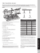
TRANSCEND RAILING
HOW TO INSTALL STANDARD CROWN OR BEVELED RAILING/CONTINUED
TREX TRANSCEND
®
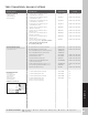
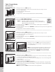
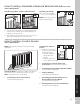
Cutting Railings
4. Measure between posts
and cut rails to same
length.
NOTES:
» If using optional rail
gaskets, subtract 1/16"
(0.15 cm) from each end.
» Attach baluster spacers to railing before cutting to
allow for cleaner cut and less work.
» When measuring, cut equal lengths from each side of
railing and baluster spacer to ensure equal spacing
of balusters per each railing section.
» In some cases, the gasket can be attached before
tightening railing to RSB.
» If gaskets are tight, use a small flat head screwdriver
to compress the tabs of the gasket if they are stuck
outside the rail
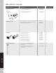
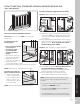
Attaching Bottom Rail (Universal or Beveled
Rail) and Foot Block
NOTES:
» REFER TO PAGE 71 FOR DETAILED
INSTRUCTIONS ON INSTALLATION OF FOOT
BLOCK (BASIC STEPS ARE SHOWN BELOW)
5a. Center foot block in Universal rail channel or on
beveled bottom rail and attach. DO NOT extend
foot block as per step 5c until all other railing
installation steps are completed.
5b. Lift bottom rail so RSBs are in the channel and
attach with self-tapping screws (provided).
5c. Telescope foot block
down and screw through
opposite sides. Place
screw plugs.
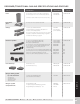
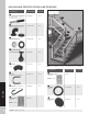
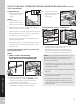
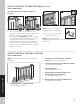
Placing Baluster Spacers and Balusters
6. Cut baluster spacers the same length as rails,
equally spaced so the holes line up.
7. Snap baluster spacer into bottom rail. Place
inverted baluster spacer on top of first baluster
spacer. Place balusters in baluster spacer holes.
NOTES: If using Round Aluminum balusters, also use
Round Aluminum baluster connectors to ensure a
tight fit of the balusters (this will help prevent
balusters from rattling).
» Install without using screws (screws are included
in connector packaging and screws are used only
with Designer Railing).
» Install bottom connector tight into Round Aluminum
baluster.
» Install top connector approximately half way into
Round Aluminum baluster.
» Round Aluminum balusters should then have a
snug fit when placing into the baluster spacers
in the horizontal position—if not adjust the depth
of the connector.
6
7
2
5c
2
3
3
1
1
5a
2
1
1
5b
2
4a