WinSystems partners with Tri-M Systems WinSystems® is pleased to be partnered with the Tri-M® industrial power supply group. Tri-M® is a leader in industrial PC/104 DC/DC power supplies. With Tri-M®’s outstanding reputation for support, we recommend all technical and RoHS inquiries regarding their modules be sent to Tri-M® directly. As always, the WinSystems Applications Engineering department is available to assist as needed. HE104 TRI-M® Technical Manual Tri-M Systems and Engineering, Inc.
PC/104 Vehicle Power Supply High Efficiency & Smart Charging Vehicle Power Supply DC to DC Convertor Manufactured by TRI-M ENGINEERING Engineered Solutions for Embedded Applications Technical Manual P/N: HE104MAN-V8 Revision: 23 June 2005 TRI-M ENGINEERING 1407 Kebet Way, Unit 100 Port Coquitlam, BC V3C 6L3 Canada http:// www.Tri-M.com Tel 604.945.9565 North America 800.665.5600 Fax 604.945.
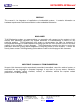
HE104MAN-V8 Manual 23 June 2005 CHAPTER 1: INTRODUCTION........................................................................................................................................4 1.1 GENERAL DESCRIPTION .....................................................................................................................................4 1.2 FEATURES .................................................................................................................................................
HE104MAN-V8 Manual 23 June 2005 PREFACE This manual is for integrators of applications of embedded systems. It contains information on hardware requirements and interconnection to other embedded electronics. DISCLAIMER Tri-M Engineering makes no representations or warranties with respect to the contents of this manual, and specifically disclaims any implied warranties of merchantability or fitness for any particular purpose.
HE104MAN-V8 Manual 23 June 2005 CHAPTER 1: INTRODUCTION 1.1 GENERAL DESCRIPTION The HE104 multiple output DC to DC 50 watt converter is a high efficiency, high performance unit that can be supplied with +5V, +12V outputs only or can include features such as, Power Management, Universal Battery Charger, AC Bus termination, -5V output, -12V output and custom output voltages from -42V to +42V.
HE104MAN-V8 Manual 23 June 2005 1.2 Features • DC to DC convertor for PC/104 bus equipped products. • “Load Dump” transient suppression on input power supply. • Operates from 6VDC to 40VDC input. • “Stacks” onto the PC/104 bus. • Passthrough or non-passthrough 8 bit and 16 bit versions. • 5V, 12V standard, -12V, -5V and battery charger optional. • Highly compact, 100 percent PC/104 conforming. • AC bus termination available. • Screw terminals provide off-board connection to output voltages.
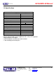
HE104MAN-V8 Manual 23 June 2005 1.3 Specifications Model Power Supply Specifications HE104 5V output* 12V output -5V output -12V output Input Voltage Range Load Regulation ** Line Regulation ** Output temp.drift ** Switching Frequency Max. Input Transient Output Ripple ** Conducted Susceptibility ** Efficiency ** Temp Range Quiescent current *** Size, PC/104 form factor compliant **** 10A 2A 400mA 500mA 6 to 40V <60mV +40mV <40mV 75kHz 125V for 100msec <20mV >57db up to 95% -40 to 85C 2mA 3.55"W.x 3.
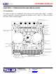
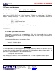
HE104MAN-V8 Manual 23 June 2005 CHAPTER 2: CONFIGURATION AND INSTALLATION 2.1 Introduction This chapter describes the configuration and installation of the HE104 power supply. In addition, section 2.2 provides a formula to calculate the available +5VDC. Figure 2-1 shows the HE104 connectors, jumpers and other options. Tri-M Engineering 1407 Kebet Way, Unit 100 Port Coquitlam, BC V3C 6L3 Canada Tel: Fax: E-mail: Web site: 800.665.5600, 604.945.9565 604.945.9566 info@tri-m.com www.tri-m.
HE104MAN-V8 Manual 23 June 2005 2.2 Power Considerations Usable +5V output =10A – (I [-5] + I [-12] • 2.4 + I [12] • 2.4) 0.8 The +5V switching regulator is rated at 10A maximum output however, the +5V output, supplies power to the +12VDC, -5VDC and –12VDC regulators. To obtain the usable range of +5V output, “derate” according to the use of +12VDC, -5VDC and –12VDC. Use the following formulae to calculate the maximum usuable output.
HE104MAN-V8 Manual 23 June 2005 2.3.2 Output Power Connector Output power is available for non-PC/104 use via connector CN2. - Terminal 1: +5VDC output Terminal 2: Common Terminal 3: +12VDC Terminal 4: -12VDC output (optional) Terminal 5: -5VDC output (optional) 2.3.3 Battery Power Connector (Optional) Batteries are connected to the screw terminal block, CN3. The HE104 accepts DC battery voltages in the range of 6.5V to 40DVC through the Battery Power Connector.
HE104MAN-V8 Manual 23 June 2005 Examples of NMH0515S can generate the following voltages: - 15V by connecting NMH “0V” to HE104 common -30V by connecting NMH +V to Common +30V by connecting NMH –V to Common +42V by connecting NMH –V to +12V output Note: When batteries or external signals are connected to CN3 the Plug-IN Boost regulator (VR3) cannot be installed. See section 2.3.4 2.4 Bus Termination (Optional) AC bus termination minimizes power consumption as it improves the reliability of the bus.
HE104MAN-V8 Manual 23 June 2005 2.6.2 +5VDC Low Q/ Noise (Q=quiescent) This jumper allows the +5VDC regulator IC1 to be changed from the low ripple noise mode into the low quiescent power mode. This option is most likely to be used when absolute minimum power consumption must be maintained such as, when operating off a limited battery source. It is recommended that the +12vDC Low Noise mode be selected whenever the +5VDC Low Q. mode is not required.
HE104MAN-V8 Manual 23 June 2005 Figure 2.3, HE104 Mezzanine Connectors Connector CN5 Pinout Connector CN6 Pinout 1. +5V 10. +5V 1. PM104-P1 10. Main Pwr. Input 2. Common 9. Common 2. Common 9. Common 3. +Battery Input 8. Main Pwr Input 3. PM104-P7 8. PM104-P2 4. Ext. Signal 1 7. +12V 4. PM104-P6 7. PM104-P3 5. Ext. Signal 2 6. -5V 5. PM104-P5 6. PM104-P4 2.
HE104MAN-V8 Manual 23 June 2005 Figure 2-2, Interrupt IRQ Selection 2.8 Power Management Controller PM104 (optional) The Power Management Controller (PM104) is a microcontroller “plug-in” module for timed on-off control of the HE104, control of the optional battery charger and generation of interrupts to the PC/104 host CPU. The PM104 is programmed in a high level “controller basic language” called Pbasic.
HE104MAN-V8 Manual 23 June 2005 Table 2.
HE104MAN-V8 Manual 23 June 2005 2.10 HE104 Efficiency and Heat Dissipation Calculation The average efficiency for the +5V output of the HE104 is 90 percent. The efficiency, however, at any specific input voltage, output load and ambient temperature many be higher or lower. Typical efficiency is between 88 and 94 percent. Best efficiency occurs at mid input voltage ranging from16 to 18V, mid output loads are from 20 to 30 watts and a low heat sink temperature.
HE104MAN-V8 Manual 23 June 2005 CHAPTER 3: THEORY OF OPERATION 3.1 Input power protection Input power is connected to the screw terminal block, CN1, which is removable from the socket connector on the circuit board. A 10 ampere “pico” fuse F1 limits the current draw from the power source. A series of devices, (toroid coil L3, transorb D4 and filter capacitors, C8A,C8B and C8D) filters and clamps the input power. Transorb D4 is a 5KVA, heavy-duty, transient suppressor.
HE104MAN-V8 Manual 23 June 2005 3.3 Switching regulator, +12VDC A switching regulator IC2, generates the +12VDC output and operates in a “Boost” mode switching regulator configuration which uses inductor coil L2, mosfet Q7, schottky diode Q6, input filter capacitors C9A, C9B, C9C and output filter capacitors C15A and C15B. Capacitors C9A, C9B and C9C work as an output filter for the +5VDC and as an input filter for the +12VDC regulator IC2.
HE104MAN-V8 Manual 23 June 2005 3.5 Filter Capacitors At 10kHz and above, the impedance of filter capacitors is essentially their effective series resistance (ESR) and this parasitic resistance limits the filtering effectiveness of the capacitors. The filter capacitors absorb the “switching ripple” current with their 100m0hm ESR that absorbs a 5A ripple current and will dissipate 2.5W of heat. The capacitors used for filtering in the HE104 are organic semiconductor (OS-CON) capacitors.
HE104MAN-V8 Manual 23 June 2005 Note: that only the ESR of the output capacitor is used in the formula. It is assumed that the capacitor is purely resistive at the frequencies about 20kHz. Worst case output ripple is at highest input voltage. Ripple voltage is independent of load (for continuous mode). Example Vout = 5V, Vin = 28V, L1 = 55uH, frequency = 50kNz and three 330uF capacitor with 27 mohm ESR in parallel. 0.009 • 5• (1- ( 5 )) Vp –p = 28 55 • 10E6 • 0.5 • 10E5 3.
HE104MAN-V8 Manual 23 June 2005 APPENDIX 1: HE104, +5V Regulator Block Diagram: 1.1 HE104, +12V, -12V, &-5V Regulator Block Diagram Tri-M Engineering 1407 Kebet Way, Unit 100 Port Coquitlam, BC V3C 6L3 Canada Tel: Fax: E-mail: Web site: 800.665.5600, 604.945.9565 604.945.9566 info@tri-m.com www.tri-m.
HE104MAN-V8 Manual 23 June 2005 Tri-M Engineering 1407 Kebet Way, Unit 100 Port Coquitlam, BC V3C 6L3 Canada Tel: Fax: E-mail: Web site: 800.665.5600, 604.945.9565 604.945.9566 info@tri-m.com www.tri-m.
HE104MAN-V8 Manual 23 June 2005 APPENDIX 2: ADVANTAGES OF USING AC TERMINATION: One of the requirements of embedded electronics is low power consumption. One method of reducing power is to reduce the drive current available to power the expansion bus. With over 80 signal lines, any reduction in current load would have a large impact on overall requirements. The PC/104 Consortium Guidelines for the expansion bus specify drive current can be as low as 4mA.
HE104MAN-V8 Manual 23 June 2005 APPENDIX 3: Installation Hints for the HE104 Power Supply: 1. To minimize noise induced into the power supply, connect the HE104 power supply direct to the power supply source (battery) with “dedicated” wires. This makes use of the vehicle battery as a filter. 2. Always use large gauge hook-up wires to connect the HE104 power supply to the vehicle power source (battery). This minimizes any voltage drop caused by the resistance of the wire.
HE104MAN-V8 Manual 23 June 2005 (P6KE or 1.5KE) will not survive the high-energy discharge of a “load dump”. Special automotive suppressors must be used to use up the 20A to 30A peak currents being shunted. Several manufacturers, such as Motorola, Harris and Seimens, manufacture suppressors specifically for automotive applications. Some devices provide “zener diode” style protection, while others provide “back to back zener diode” bidirectional protection.
HE104MAN-V8 Manual 23 June 2005 maximum charge time, negative delta V. The user must set these for the type and size of battery to be charged. Typically charge currents will be 1/3 to 1/6 of battery capacity and trickly charge current 1/20 to 1/30 of battery capacity. Addition of a battery temperature sensor will allow charge termination when elevated battery temperatures (which indicates battery is fully charged).
HE104MAN-V8 Manual 23 June 2005 A variety of temperature sensors can be connected including thermistors and conditioned sensors such as LM35s. The LM35 series is particularly nice because their output voltage is directly proportional to temperature (ie 10mV/C or 10mV/F). In any case, the OEM can “experiment” to determine what works best in their application. 3.
HE104MAN-V8 Manual 23 June 2005 7. Sample Battery Charging Program Listing The following program listing is intended for use as a guide to customizing the BC104 and PM104 operation. Additional functions and features can be added including temperature monitoring are left up to the OEM to implement.
HE104MAN-V8 Manual 23 June 2005 ‘D1 = 0, D0 = 0 channel 0 input, pin3 of connector CN3 ‘D1 = 0, D0 = 1 channel 1 input, pin4 of connector CN3 ‘1. on max cell voltage ‘2. on time ‘3. –ve delta V ‘4.
HE104MAN-V8 Manual 23 June 2005 Let DIOp =D0 Pulsout CLK.2 Low CS1 ‘next bit of command ‘Activate the LTC1594 ‘Get ready for input from LTC 1594 Input DIO Pulsout CLK.2 Input DIO Pulsout CLK.2 Let AD = 0 For Adbits = 1 to 13 Pulsout CLK.2 Let AD = AD*2 +DIOp Next Adbits High CS1 Return ‘Dummy statement for delay ‘Sampling requires two clocks ‘Clear old ADC result. ‘Get null bit + 12 data bits. ‘Clock next data bit in. ‘Shift AD left, add new data bit. ‘Get next data bit.
HE104MAN-V8 Manual 23 June 2005 Let Bat1_chrg = 0 Main_Batt1: Low PSU_OnOff If Bat1_Chrg = 1 then Batt_Trickle Goto Bat_Chrg Batt_Trickle: ‘debug “trickle” gosub Chk_Pwr let D1 = 0 let D0 =0 gosub Convert let Batt_V =AD PWM Chrg_Limit, Trickle_LVL, 1000 Low Chrg_Limit Goto Main_Batt1 Chk_Pwr: Let D1 = 1 Let D0 = 0 Gosub Convert ‘debug AD, Batt_V if AD < Batt_V then No_ Power return No_Power: ‘debug “no_pwr” pause 50 let Bat1_Chrg = 0 PWM Chrg_Limit, 0.
HE104MAN-V8 Manual 23 June 2005 Distributed By: Tri-M Engineering 1407 Kebet Way, Unit 100 Port Coquitlam, BC V3C 6L3 Canada Tel: Fax: E-mail: Web site: 800.665.5600, 604.945.9565 604.945.9566 info@tri-m.com www.tri-m.