MOPS/586 Technical Manual Rev. 1.4 JUMPtec Industrielle Computertechnik AG Brunnwiesenstraße 16 94469 Deggendorf/ Germany Tri-M Systems Inc., 6-1301 Ketch Court, Coquitlam, B.C., V3K 6X7, Canada Phone: (604) 527-1100, (800) 665-5600 Fax: (604) 527-1110 Email: info@Tri-M.com Web: www.Tri-M.
MOPS/586 Table of Contents Table of Contents TABLE OF CONTENTS.......................................................................................................................................... 2 USER INFORMATION ............................................................................................................................................ 4 TRADEMARKS ........................................................................................................................................
MOPS/586 Table of Contents FLOPPY CONNECTOR ............................................................................................................................................... 30 IDE CONNECTOR FOR 2,5" HARD DISK ..................................................................................................................... 31 ETHERNET CONNECTOR ...........................................................................................................................................
MOPS/586 User Information User Information Copyright 1997 JUMPtec® Industrielle Computertechnik AG. In this document JUMPtec® Industrielle Computertechnik AG will also be referred to by the short form "JUMPtec®". The information in this document has been carefully checked and is believed to be accurate and reliable. However, no responsibility is assumed for inaccuracies. Furthermore, JUMPtec® reserves the right to make changes to any portion of this manual to improve reliability, function or design.
MOPS/586 User Information Warranty Each board is tested carefully and thoroughly before being shipped. If, however, problems should occur during the operation, please check your user specific settings of all boards included in your system. This is often the source of the fault. If a board is defective, it can be sent to your supplier for repair. Please take care of the following steps: 1. The board returned should have the factory default settings since a test is only possible with these settings. 2.
MOPS/586 Features Features • Processor ® AMD Am5x86 with 133 MHz internal Clock and 16 kByte write-back-Cache • Chipset ALI 1489/1487 PCI Chipset • Power Supply 5V only supply • Memory 4 MB onboard and 4/8/16/32MB 5V-DIMM module DRAM with Fast Page Mode or EDO DRAM on the lower SO-DIMM-Connector • Ethernet 10BaseT (Twisted Pair) • Two serial ports, (COM1 and COM2) standard RS232C serial ports with FIFO, 16550 compatible • Parallel port, LPT1 With ECP/EPP-support • Floppy-interface • EIDE-PCI-hard disk-in
MOPS/586 I/O Map I/O Map The I/O-port addresses of the processor module MOPS/586 are functionally identical with a standard PC/AT.
MOPS/586 Memory Map for BIOS, SSD and JRC Support Memory Map for BIOS, SSD and JRC Support The BIOS includes two special extensions to support the onboard silicon state disk and Jumptec Remote Control. If the SSD is enabled in setup or the JRC client finds a host the code of the bios extension will be copied into shadow ram. The location where the biosextension is placed is automatically determined by the system bios .
MOPS/586 Onboard SSD (DOS-compatible) Expanded Memory Map The user can convert (up to 20Mbytes) Extended Memory into Expanded Memory (EMS). The selected Expanded Memory is devided into 16KByte pages, of which four can be mapped into the EMS-frame. The EMSframe is located within the first 1MByte address space and has a length of 64KByte. The start address of the EMS-page can be selected between CC000h and E0000h in steps of 16KBytes.
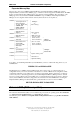
MOPS/586 Block Diagram Block Diagram BIOS RTC LPT1 IO-Controller EIDE COM1 COM2 ALI Chipset DRAM Cache CPU EthernetController 10baseT ISA-Con. Tri-M Systems Inc., 6-1301 Ketch Court, Coquitlam, B.C., V3K 6X7, Canada Phone: (604) 527-1100, (800) 665-5600 Fax: (604) 527-1110 Email: info@Tri-M.com Web: www.Tri-M.
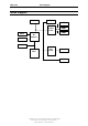
MOPS/586 Connector Arrangement Connector Arrangement Tri-M Systems Inc., 6-1301 Ketch Court, Coquitlam, B.C., V3K 6X7, Canada Phone: (604) 527-1100, (800) 665-5600 Fax: (604) 527-1110 Email: info@Tri-M.com Web: www.Tri-M.
MOPS/586 BIOS-Description BIOS-Description The Standard AMI-BIOS is located in the Flash EPROM onboard. This device has 8 bit wide access. 16 bit access is enabled by the shadow RAM feature (Standard). RTC-CMOS setup menu During boot sequence the CMOS setup can be entered by pressing the -key while the memory test is in progress.
MOPS/586 BIOS-Description • WPcom (starting write precompensation cylinder) • Sec (number of sectors) Parameter Type Cylinders Heads Write Precompensation Landing Zone Sectors Size Description The number for a drive with certain identification parameters. The number of cylinders in the disk drive. The number of heads. The size of a sector gets progressively smaller as the track diameter diminishes. Yet each sector must still hold 512 bytes.
MOPS/586 BIOS-Description Advanced CMOS Setup Quick Boot Set this option to Enabled to instruct AMIBIOS to boot quickly when the computer is powered on. This option replaces the former Above 1 MB Memory Test Advanced Setup option. The settings are: Setting Disabled Enabled Description AMIBIOS tests all system memory. AMIBIOS waits up to 40 seconds for a READY signal from the IDE hard disk drive. AMIBIOS waits for 0.
MOPS/586 BIOS-Description Wait For 'F1' if Error If this option is Enabled the system will wait on power up for the user to press the key on any occurring error. The Optimal and Fail Safe default settings are Disabled. Hit ‚Del‘Message Display If this option is Enabled the system will display the String „Hit DEL if you want to run Setup“ on the screen while accepting the DEL key to enter setup. If the option is set to Disabled the string want be displayed.
MOPS/586 BIOS-Description Power Management Setup Power Management/APM If this option is Disabled, none of the below listed options are available, the system doesn't provide you with power save features. The Optimal and Fail Safe default settings are Disabled. Instant On Support Instant On is a Power Managment Software for Windows 95. Must be Enabled to support this Software. The Optimal and Fail Safe default settings are Disabled.
MOPS/586 BIOS-Description Peripheral Setup Onboard IDE This option enables the onboard IDE controller. The settings are Disabled and Enabled. The Optimal and Fail Safe default settings are Enabled. Onboard FDC This option enables the floppy drive controller on the motherboard. The settings are Enabled or Disabled. The Optimal and Fail Safe default settings are Enabled. Onboard Serial Port1 This option enables serial port 1 on the motherboard and specifies the base I/O port address for serial port 1.
MOPS/586 BIOS-Description This option enables the silicon state disk as either drive 80h, 81h, 82h, or 83h (C, D, E or F). The settings are Disabled, 80h, 81h,82h, 83h. The Optimal and Fail Safe default settings are Disabled. SSD Write Protect This option allows to write protect the silicon state disk. The settings are Disabled and Enabled. The Optimal and Fail Safe default settings are Disabled.
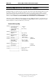
MOPS/586 BIOS-Description AMIBIOS Configuration Screen AMIBIOS System Configuration (C) 1985-1996, American Megatrends Inc., Main Processor : Am5x86 (X5) Base Memory Size : 640KB Math Processor : Built-In Ext. Memory Size : 3072KB Floppy Drive A: : 1.
MOPS/586 Hardware Description Hardware Description ALI-Chipset Features The MOPS/586 Board operates with the chipset ALI 1489/87, which provides following features: • • • • • • • 32 bit PCI Interface integrated DRAM controller integrated PMU controller integrated PCI to ISA bridge (fully compliant to PCI 2.
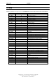
MOPS/586 Hardware Description Interrupts IRQ0 IRQ1 IRQ2 IRQ3 IRQ4 IRQ5 IRQ6 IRQ7 IRQ8 IRQ9 IRQ10 IRQ11 IRQ12 IRQ13 IRQ14 IRQ15 System Timer Keyboard Cascade COM 2 COM 1 Ethernet (default) Floppy LPT 1 Clock/Calendar Available Available Available Available Numeric-processor EIDE Channel 1 Available note (1) note (1) note (2) notes (2) notes (2) note (2) Notes: (1) if serial ports are disabled via system bios, these interrupts are available for other devices.
MOPS/586 Hardware Description The JIDA Standard ® JIDA is the abbreviation for JUMPtec Intelligent Device Architecture. Every board with onboard BIOS extension shall support the following function calls, which supply information about the board. JIDA functions are called via Interrupt 15h with AH=EAh, AL=function number, DX=4648h (security word), CL=board number (starting with 1). The interrupt will return with CL#0, if a board with the number specified in CL does not exist.
MOPS/586 Hardware Description Get Manufacturing Date Input: Int 15h AX = EA02h CL = Board number Output: CL=0: Board present CL≠0: Board not present BX = Manufacturing date Description If CL=0 and DX=6B6Fh, then BX=Manufacturing date. Date format is the same as used for DOS files: Bit0..4: Day Bit5..8: Month Bit9..
MOPS/586 Hardware Description Read Running Time Meter Input: Int 15h AX = EA07h CL = Board number Output: CL=0: Board present CL≠0: Board not present BX=Running time (hours) CH=Overflow counter ReadBoot Counter Input: Int 15h AX = EA08h CL = Board number Output: CL=0: Board present CL≠0: Board not present BX = Boot counter Get JIDA Revision Level Input: AX CL Int 15h = EA09h = Board number DX = 4648h DX=6B6Fh: Function successful DX≠6B6Fh: Fn.
MOPS/586 Hardware Description Watchdog Extension With the aid of a special Interrupt 15h function, the watchdog on a JUMPtec board can be controlled very easily. The respective functions have the following calling conventions: Watchdog init Input: Output: Description: Watchdog trigger Input: Output: Description: Int 15h 00h AH = E0h AL = 00h BX = timeout in 0.2sec increments CX = delay in 0.
MOPS/586 Network Operation Returns Example no mov mov mov mov int ax,0E000h bx,5 cx,5 dx,0 15h ; Watchdog set ; 5*0,2s = 1s Timeout ; 5*0,2s = 1s Delay ; after Timeout and Delay generate RESET Network Operation Overview The Crystal LAN™ CS8900 ISA Ethernet Adapter from Crystal Semiconductor follows IEEE 802.3 standards and supports half- or full-duplex operation in ISA bus computers on 10 Mbps Ethernet networks. The driver can be download from the webpage: http://www.jump.
MOPS/586 Specifications Specifications Mechanical Specifications PC/104 Bus connector: 2 pieces of 2*32 pin male and 2*20 pin male connector Module-dimensions: length * width 95 mm * 90 mm (3,7" * 3,5 ") Electrical Specifications Supply voltage: 5V DC +/- 5% Supply voltage ripple: 100 mV peak to peak 0 - 20 MHz Supply current (maximal): ( Σ max.
MOPS/586 Peripheral Interface Peripheral Interface Keyboard, Reset, Battery, Speaker Pin Signal name Function 1 2 3 4 5 6 7 8 9 10 SPKR GND POWERGOOD /KLOCK KDATA KCLK GND VCC VBAT POWERGOOD speaker output ground reset input keyboard lock keyboard data keyboard clock ground +5V VBAT input (3,6V) reset input 5-pin diode keyboard adapter 6-pin minidin keyboard adapter (PS2) 2 1 4 5 1 5 3 4 /KLOCK (keyboard lock) input on CPU modules output on any other module input to the keyboard controller inpu
MOPS/586 Peripheral Interface 1 (Speaker) 2 (GND) 3,10 (PowerGood) 4 (/KLOCK) 5 (KDATA) 6 (KCLK) 5 7 (GND) 3 2 4 1 8 (+ 5V) 9 (VBAT) Serial Port COM 1, 2 (RS232C) Pin Signalname In / Out DSUB-25 DSUB-9 (need Adapter) (need Adapter) 1 DCD In 8 1 2 DSR In 6 6 3 RxD In 3 2 4 RTS Out 4 7 5 TxD Out 2 3 6 CTS In 5 8 7 DTR Out 20 4 8 RI In 22 9 9 GND -7 5 10 +5V ---For signal description please refer additional literatur.
MOPS/586 Peripheral Interface Parallel Port LPT 1 Pin Signalname Function In / Out DSUB-25 (need Adapter) 1 2 3 4 5 6 7 8 9 10 11 12 13 14 15 16 17 NC 18 - 25 18 - 25 18 - 25 18 - 25 1 /Strobe Out 3 Data 0 I/O 5 Data 1 I/O 7 Data 2 I/O 9 Data 3 I/O 11 Data 4 I/O 13 Data 5 I/O 15 Data 6 I/O 17 Data 7 I/O 19 /ACK in 21 BUSY in 23 PAPER out in 25 SEL out in 2 /AUTOFD out 4 /ERROR in 6 /INIT out 8 SEL in out 26 Vcc +5V -10,12 GND Signal Ground -14,16 GND Signal Ground -18,20 GND Signal Ground -22,24 GND
IDE Connector for 2,5" Hard Disk Pin 1 3 5 7 9 11 13 15 17 19 21 23 25 27 29 31 33 35 37 39 41 43 Signal /RESET D7 D6 D5 D4 D3 D2 D1 D0 GND NC /IOW /IOR NC NC IRQ14 SA1 SA 0 /CS0 /HDLED VCC GND Pin 2 4 6 8 10 12 14 16 18 20 22 24 26 28 30 32 34 36 38 40 42 44 Signal GND D8 D9 D10 D11 D12 D13 D14 D15 NC GND GND GND BALE GND /IOCS16 NC SA2 /CS1 GND VCC NC For signal description please refer additional literatur.
MOPS/586 Peripheral Interface Power Connector Pin 1 2 3 4 5 6 7 8 Pin function GND +5V keypin +12V -5V -12V GND +5V Power Pins The MOPS/586 is a +5 V only module. Nevertheless the power connector offers the possibility to supply with the additional voltages +12V, -12V and -5V which may be needed by other boards in the PC/104 system.
MOPS/586 Peripheral Interface PC/104-Connector Specification XT Bus Pin Signal Name Pin Signal Name A1 A2 A3 A4 A5 A6 A7 A8 A9 A10 A11 A12 A13 A14 A15 A16 A17 A18 A19 A20 A21 A22 A23 A24 A25 A26 A27 A28 A29 A30 A31 A32 /IOCHCK SD7 SD6 SD5 SD4 SD3 SD2 SD1 SD0 IOCHRDY AEN SA19 SA18 SA17 SA16 SA15 SA14 SA13 SA12 SA11 SA10 SA9 SA8 SA7 SA6 SA5 SA4 SA3 SA2 SA1 SA0 GND B1 B2 B3 B4 B5 B6 B7 B8 B9 B10 B11 B12 B13 B14 B15 B16 B17 B18 B19 B20 B21 B22 B23 B24 B25 B26 B27 B28 B29 B30 B31 B32 GND RESETDRV +5V IR
MOPS/586 Literature, Standards, Links Literature, Standards, Links PC/104-Bus • PC/104 Specification Version 2.3 June 1996 PC/104 Consortium; www.pc104.org • Embedded PCs Markt&Technik GmbH, ISBN 3-8272-5314-4 (german) ISA-Bus, Standard PS/2 - Connectors • ISA System Architecture Addison-Wesley Publishing Company • Edward Solari, AT BUS Design IEEE P996 Compatible, Annabooks San Diego CA. ISBN 0-929392-08-6 www.annabooks.com • PC Handbook, Sixth Edition, John P. Choisser and John O.
MOPS/586 Document Revision History Document Revision History Filename P488M210 P488M211 P488M212 P488M213 P488M214 Date 10.09.98 16.09.98 28.09.98 10.01.99 22.12.99 Edited by KW KW KW KW Ba Alteration to preceding revision Created Add SSD Onboard-DRAM, superMOPSpro replaced Add L1-Cache changed typ. current in chapter Electrical specifications, changed IRQ10 and IRQ11 to available in chapter Interrupts Tri-M Systems Inc., 6-1301 Ketch Court, Coquitlam, B.C.