
Install Instructions

16
Boiler Piping
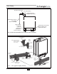
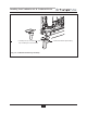
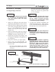
Additional Limit Control
If a Low Water Cut Off (LWCO) is required by
certain local jurisdictions or when the boiler is
installed above the system piping, the follow-
ing guidelines must be followed:
- The LWCO must be designed for water
installations, electrode probe-type is
recommended.
- The LWCO must be installed in a tee
connection on the boiler supply piping
above the appliance.
- Wiring of the LWCO to the CHAL-
LENGER should be done in series with
the 120 VAC service to the appliance .
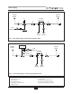
If the installation is to comply with ASME
CSD-1 or Canadian requirements, an addition-
al high temperature limit may be needed.
Consult local code requirements to determine
compliance. The limit should be installed as
follows:
- Install the limit in the boiler supply pip-
ing between the boiler and any isolation
valve.
- Maximum set point for the limit is
200ºF [93ºC].
- Wiring of the limit device to the CHAL-
LENGER should be done in series with
the 120 VAC service to the appliance.
Backflow Preventer
- Use a backflow preventer valve in the
make-up water supply to the appliance
as required by local codes.
Boiler System Piping Applications
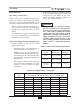
It is required on all piping applications
to utilize a primary/secondary piping
arrangement. Maintain the minimum
boiler flow rate, see Graphs 5-10 on
pages 69-71.
Expansion Tank and Makeup Water
Ensure the expansion tank is properly sized for
the boiler water volume (approximately 1 gal-
lon [4 L]) and the system water volume and
temperature.
Undersized expansion tanks will cause
system water to be lost through the pres-
sure relief valve and cause additional
makeup water to be added to the system.
Eventual boiler heat exchanger failure
can result due to this excessive makeup
water addition.
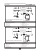
The expansion tank must be located as shown
in Fig. 5 and Fig. 6 on page 18 when using a
primary/secondary piping arrangement or as
per recognized design methods. Refer to the
expansion tank manufacturer instructions for
additional installation details.
Connect the expansion tank to an air separator
only if the air separator is located on the suc-
tion side (inlet) of the system circulator.
Always locate and install the system fill con-
nection at the same location as the expansion
tank connection to the system.
Diaphragm Expansion Tank
Always install an automatic air vent on the top
of the air separator to remove residual air from
the system.
BEST PRACTICE
CAUTION