
Instinct Installation Manual

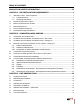
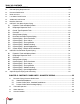
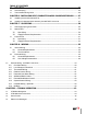
Table Of Contents
- SOLO 11 0 -15 5 -199 & COMBI 155 -19 9
- • To maintain the safety & longevity of your appliance, read and follow the maintenance schedule information throughout this manual.
- INTENTIONALLY LEFT BLANK
- INDEX OF ILLUSTRATIONS AND TABLES
- PRODUCT AND SAFETY INFORMATION
- DANGER
- DANGER
- DANGER
- DANGER
- DANGER
- DANGER
- DANGER
- DANGER
- 2.7. Carbon Monoxide Detector Installation
- 2.8. Commonwealth of Massachusetts Installation Requirements
- INTENTIONALLY LEFT BLANK
- CHAPTER 3 - UNIT PREPARATIONS
- NOTICE
- NOTICE
- NOTICE
- NOTICE
- NOTICE
- NOTICE
- NOTICE
- NOTICE
- NOTICE
- NOTICE
- NOTICE
- NOTICE
- NOTICE
- NOTICE
- NOTICE
- NOTICE
- DANGER
- DANGER
- DANGER
- NOTICE
- 9.2. CTRLMax Menu Structure
- 9.3. Home Screen
- 9.4. Status Line Messages
- 9.5. Main Menu
- 9.6. EZ Setup
- 9.7. Heating EZ Setup
- 9.8. Domestic Hot Water EZ Setup - INSTINCT Solo Units
- 9.9. Domestic Hot Water EZ Setup - INSTINCT Combi Units
- 9.10. Altitude Setup
- 9.11. EZ Setup Reset
- 9.13. CH/DHW Operation
- 9.14. Boiler Information
- INTENTIONALLY LEFT BLANK
- CHAPTER 10 - START-UP PREPARATION
- NOTICE
- NOTICE
- NOTICE
- NOTICE
- NOTICE
- DANGER
- DANGER
- DANGER
- DANGER
- DANGER
- 17.9. Check Boiler System
- 17.10. Check Expansion Tank
- 17.11. Check Boiler Relief Valve
- 17.12. Inspection of Ignitor
- 17.13. Check Ignition Cable and Ground Wiring
- 17.14. Check Control Wiring
- 17.15. Check Control Settings
- 17.16. Perform Start-up and Checkout Proce- dures
- 17.17. Check Burner Flame
- 17.18. Check Flame Signal
- 17.19. Check Combustion Levels
- 17.20. Check Flue Gas Temperature
- 17.21. Clean Heat Exchanger
- 17.22. Check Carbon Monoxide Detectors
- 17.23. Review With Owner
- 17.24. Torque Specifications Table
- NOTICE

ix
INDEX OF ILLUSTRATIONS AND TABLES
Fig. 1 - All Combustion Air from Adjacent Indoor Spaces through Indoor Combustion Openings ....... 7
Fig. 2 -All Combustion Air from Outdoors Through One Permanent Air Opening ................................ 7
Fig. 3 - All Combustion Air from Outdoors Through Ventilated Attic ................................................ 8
Fig. 4 - All Combustion Air from Outdoors Through Horizontal Ducts .............................................. 8
Fig. 5 - Accessories ............................................................................................................................ 13
Fig. 6 - INSTINCT Pressure Relief Valve, Drain Valve, T&P Gauge Installation .................................... 15
Fig. 7 - Piping Component Legend ..................................................................................................... 16
Fig. 8 - INSTINCT Solo Near Boiler Piping - Hydraulic Separator ....................................................... 17
Fig. 9 - INSTINCT Solo Near Boiler Piping - Closely Spaced Tees ...................................................... 18
Fig. 10 - INSTINCT Combi Near Boiler Piping - Hydraulic Separator ................................................. 20
Fig. 11 - INSTINCT Combi Near Boiler Piping - Timesaver Manifold ................................................... 21
Fig. 12 - Standard Installation of the domestic pressure relief valve ............ 23
Fig. 13 - INSTINCT Combi - Hydro-block Flow Diagram ..................................................................... 24
Fig. 14 - Condensate Drain Assembly ............................................................................................... 28
Fig. 15 - Recommended Gas Supply Piping ....................................................................................... 29
Fig. 16 - Gas Valve / Venturi Assembly - INSTINCT Solo 110 ............................................................. 32
F
ig
.
1
7
-
G
a
s
Va
l
v
e
/
Ve
nt
uri
As
se
mbly
-
IN
S
TIN
C
T
S
olo
/
C
o
mbi
1
55 ................................................
32
F
ig
.
1
8
-
G
a
s
Va
l
v
e
/
Ve
nt
uri
As
se
mbly
-
IN
S
TIN
C
T
S
olo
/
C
o
mbi
1
99
................................................
33
Fig. 19 - CTRLMax Control Module Fuse Location ............................................................................. 35
Fig. 20 - Multiple Zones - Panel Wiring with Circulators .................................................................... 36
Fig. 21 - INSTINCT Combi System Piping - Multiple Zones - Panel Wiring with Valves ..................... 37
Fig. 22 - INSTINCT Solo Boiler Factory Wiring .................................................................................. 38
Fig. 23 - INSTINCT Combi Boiler Factory Wiring ............................................................................... 39
Fig. 24 - Terminal Strip Location ...................................................................................................... 40
Fig. 25 - Low Voltage Connections ..................................................................................................... 41
Fig. 26 - CTRLMax User Interface ..................................................................................................... 43
Fig. 27 - Throttle Screw Location ....................................................................................................... 65
Fig. 28 - INSTINCT Solo Jacket Components .................................................................................... 81
Fig. 29 - INSTINCT Combi Jacket Components ................................................................................ 82
Fig. 30 - INSTINCT Solo 110 Internal Components ........................................................................... 83
Fig. 31 - INSTINCT Solo 155 Internal Components ............................................................................ 84
Fig. 32 - INSTINCT Combi 155 Internal Components ........................................................................ 85
Fig. 33 - INSTINCT Solo 199 Internal Components........................................................................... 86
Fig. 34 - INSTINCT Combi 199 Internal Components ....................................................................... 87
Fig. 35 - INSTINCT Solo 110 Burner Components .......................................................................... 88
F
ig
.
36
-
IN
S
TIN
C
T
S
olo
/
C
o
mbi
1
55 B
ur
n
e
r
C
o
mp
on
e
nt
s .............................................................
89
Fig. 37 - INSTINCT Combi 199 Burner Components ........................................................................ 90