
Instinct Venting Manual
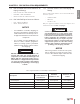

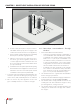
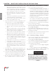

12" Min. [30.5 cm]
Radial Distance
12" [30.5 cm] (18” [ 45.7 cm] Canada)
Above the Highest
Anticipated Snow Level
Vent Termination
[30.5 cm to 61 cm]
12" Min. - 24" Max
Above Combustion
Air Inlet
Combustion Air Termination
8
CHAPTER 2
CHAPTER 2 - DIRECT VENT INSTALLATION OF VENT/AIR PIPING
Fig. 1 - Direct Vent - Vertical Termination of Vent and Combustion Air Piping.
d. At least 3 feet [0.9 m] above any forced air in-
take within 10 feet [3 m] (does not apply to the
combustion air inlet of a direct vent appliance).
e. No closer than 12” [30.5 cm] below or horizontally
from any door, window or gravity air inlet.
f. Must be at least 4 feet [1.2 m] from any elec-
tric meters, gas meters-regulators, relief valves
or other equipment. Never terminate the vent
above or below any of these items within 4 feet
[1.2 m] horizontally.
g. A minimum 12 inches [30.5 cm] horizontal spacing
from other fan assisted appliance vents. Never ter-
minate the vent above or below any fan assisted
vent within 12 inches [30.5 cm] horizontally.
7. Locate the vent and combustion air terminations in a
manner to protect from damage by foreign objects,
such as stones, balls, or buildup of leaves or sediment.
8. Do not connect any other appliance to the vent
pipe or multiple boilers to a common vent pipe.
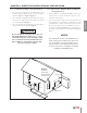
2.1.2 Direct Vent - Vent Installation - Through
the Roof
1. Vent and Combustion Air Penetration
• Vent pipe penetration through combustible or
non-combustible wall material must maintain
a minimum 1/4” [6 mm] clearance for 3” PVC/
CPVC vent or 1” [2.5cm] for 2” PVC/CPVC vent.
The diameter of the penetration hole must be
4” [10.2 cm] minimum for 2” and 3” pipe. When
using Stainless Steel Vent refer to vent manufac-
turer’s Installation Instructions for clearances.
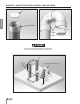
• Combustion air pipe penetration can maintain
zero clearance. The diameter of the penetration
hole should be 2-3/8” [6 cm] minimum for 2”
pipe or 3-1/2” [8.9 cm] minimum for 3” pipe.
2. The installer must use a galvanized metal thimble
for the vent pipe penetration.
3. Locate the vent and combustion air pipe penetrations to
provide clearances as described in Fig. 1 on page 8.
4. The installer must comply with all local codes for
isolating the vent and combustion air pipes as they
pass through oors, ceilings and roofs.
5. The installer must provide adequate ashing and
sealing boots sized for the vent pipe and combus-
tion air pipe.