
Instinct Venting Manual

At least 3’
Wi
t
hi
n
1
0
’
3’
Min
G
r
a
d
e
Forced air inlet
More
than 7’
4”
4”
1
2
i
n
.
m
i
n
DO NOT
terminate
above any
door, window
and air inlet
21
CHAPTER 3
CHAPTER 3 - CATEGORY IV (INDOOR AIR) INSTALLATION OF VENT/AIR PIPING
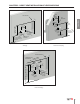
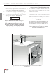
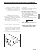
d. At least 3 feet [0.9 m] above any forced air in-
take within 10 feet [3 m] (Does not apply to the
combustion air inlet of a direct vent appliance).
e. No closer than 4 feet [1.2 m] below or horizon-
tally from any door, window or gravity air inlet.
f. Must be at least 4 feet [1.2 m] from any elec-
tric meters, gas meters-regulators, relief valves
or other equipment. Never terminate the vent
above or below any of these items within 4 feet
[1.2 m] horizontally.
g. A minimum 12 inches [30.5 cm] horizontal spacing
from other fan assisted appliance vents. Never ter-
minate the vent above or below any fan assisted
vent within 12 inches [30.5 cm] horizontally.
6. Locate the vent termination in a manner to protect
from damage by foreign objects, such as stones,
balls, or buildup of leaves or sediment.
7. Do not connect any other appliance to the vent
pipe or multiple boilers to a common vent pipe.
3.1.2 Category IV - Vent Installation - Through
the Roof
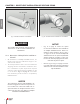
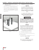
1. Vent pipe penetration through combustible or
non-combustible wall material must maintain a min-
imum 1/4” [6 mm] clearance for 3” PVC/CPVC vent or
1” [2.5 cm] for 2” PVC/CPVC vent. The diameter of the
penetration hole must be 4” [10.2 cm] minimum for
2” and 3” pipe. When using Stainless Steel Vent refer
to vent manufacturer’s Installation Instructions for
clearances.
2. The installer must use a galvanized metal thimble
for the vent pipe penetration.
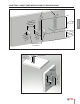
3. Locate the vent pipe penetration to provide clear-
ances as described in Fig. 15 on page 20.
4. The installer must comply with all local codes for
isolating the vent pipe as it passes through oors,
ceilings and roofs.
5. The installer must provide adequate ashing and a
sealing boot sized for the vent pipe.
3.1.3 Termination Fittings - Through the Roof
1. The vent and combustion air terminations must
include a factory supplied “bird screen” installed as
shown in Fig. 3 and Fig. 4 on page 10.
2. The combustion air piping must terminate at the
boiler with a 90º elbow.
3. The vent piping must terminate vertically with a
coupling as shown in Fig. 15 on page 20.
Do not extend the vent pipe above the roof
beyond the dimensions shown in Fig. 15 on
page 20. Extended exposure of the vent
pipe could cause condensate to freeze and
block the vent pipe, resulting in substantial
property damage, serious injury, or death.
WARNING
Fig. 16 - Termination Clearances of Category IV System