Installation and Operation Instructions Installation and Operation Instructions for Keystone Condensing Boiler Model KS Sizes 399–850 MBTU/h Water Heater Model KW Sizes 199–850 MBTU/h FOR YOUR SAFETY: This product must be installed and serviced by a professional service technician, qualified in hot water boiler and heater installation and maintenance. Improper installation and/or operation could create carbon monoxide gas in flue gases which could cause serious injury, property damage, or death.
Page 2 TABLE OF CONTENTS SECTION 1. General Information Section 6B. Water Connections - KW Water Heater 1.1 1.2 1.3 1.4 1.5 1.6 6B.1 6B.2 6B.3 6B.4 6B.5 Introduction ...................................................... 4 Model Identification ......................................... 4 Appliance Overview ......................................... 4 Warranty .......................................................... 8 Unpacking ....................................................... 8 Dimensions .......
Keystone Boilers and Water Heaters Page 3 SECTION 9. Modes of Operation SECTION 11. Maintenance 9.1 9.2 9.3 11.1 11.2 9.4 9.5 9.6 9.7 9.8 9.9 9.10 Hydronic Heating Demand ............................ 38 Hydronic Heating with Outdoor Reset ........... 38 Hydronic Heating with Domestic Hot Water (DHW) Priority ..................................... 38 Hydronic Heating Using External Modulation Control ........................................ 38 Hydronic Heating Using Local Lead-Lag/ Cascading Feature ..
Page 4 SECTION 1. General Information IMPORTANT: The inlet gas pressure to the appliance must not exceed 13" W.C. (3.2kPa). All installations must be made in accordance with 1) American National Standard Z223.1/NFPA54-Latest Edition “National Fuel Gas Code” or 2) CSA B149.1 “Natural Gas and Propane Installation Code” and with the requirement of the local utility or other authorities having jurisdiction. Such applicable requirements take precedence over the general instructions contained herein.
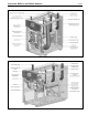
Keystone Boilers and Water Heaters Figure 1. Location of Components, Size 199. Figure 2. Location of Components, Size 285.
Page 6 Figure 3. Location of Components, Size 399. Figure 4. Location of Components, Size 500.
Keystone Boilers and Water Heaters Figure 5. Location of Components, Size 600. Figure 6. Location of Components, Sizes 750 and 850.
Page 8 1.4 Warranty 1.5 Unpacking Triangle Tube’ Keystone appliances are covered by a limited warranty. The owner should complete the warranty registration at www.TriangleTube.com. All warranty claims must be made to an authorized Triangle Tube representative. Claims must include the serial number and model (this information can be found on the rating plate), installation date, and name of the installer. Shipping costs are not included in the warranty coverage.
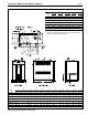
Keystone Boilers and Water Heaters Page 9 W L CM IN H CM IN AIR INLET CM IN CM 3 7.6 VENT SIZE IN IN CM 199 25 64 26¾ 68 38¼ 97 285 25 64 26¾ 68 38¼ 97 4½ 11 4½ 11 3 7.6 399 25 64 31½ 80 38¼ 97 4½ 11 4½ 11 500 25 64 37¾ 96 38¼ 97 4½ 11 4½ 11 600 25 64 37¾ 96 38¼ 97 4½ 11 4½ 11 750 25 64 51 130 38¼ 97 4½ 11 6½ 17 850 25 64 55¼ 130 38¼ 97 4½ 11 6½ 17 Dimensions are nominal and are shown in inches, cm.
Page 10 SECTION 2. Locating the Appliance 2.1 Locating the Appliance Keystone is for indoor installations only. The appliance should be located to provide clearances on all sides for maintenance and inspection. It should not be located in an area where leakage of any connections will result in damage to the area adjacent to the appliance or to lower floors of the structure.
Keystone Boilers and Water Heaters Page 11 SECTION 3. Venting and Combustion Air 3.1 Combustion Air Keystone boilers and water heaters must have provisions for combustion and ventilation air in accordance with the applicable requirements for Combustion Air Supply and Ventilation in the National Fuel Gas Code, ANSI Z223 1; or in Canada, the Natural Gas and Propane Installation Code, CSA B149.1. All applicable provisions of local building codes must also be adhered to.
Page 12 Use ABS, PVC, CPVC or galvanized pipe for the combustion air intake (see Table 4), sized per Table 2. Route the intake to the boiler as directly as possible. Seal all joints. Provide adequate hangers. The unit must not support the weight of the combustion air intake pipe. Maximum linear pipe length allowed is shown in Table 2. Subtract 5 allowable linear ft. (1.5m) for every elbow used. The connection for the intake air pipe is at the top of the unit (see Figure 8).
Keystone Boilers and Water Heaters IMPORTANT NOTE ABOUT COMMON VENTING: A single vent that is shared by multiple Keystone units MUST be engineered by a competent venting specialist, and involves the selection of draft inducing equipment, hardware and controls to properly balance flue gas pressures. Do not common vent Keystone units unless the vent system meets this requirement. Keystone units are never permitted to share a vent with Category I appliances. A condensate drain trap is built into Keystone.
Page 14 3.3 Locating Vent & Combustion Air Terminals 3.3.1 Side Wall Vent Terminal The appropriate TriangleTube side wall vent terminal must be used. The terminal must be located in accordance with ANSI Z223.1/NFPA 54 and applicable local codes. In Canada, the installation must be in accordance with CSA B149.1 or .2 and local applicable codes. Consider the following when installing the terminal: 1. Figure 11 shows the requirements for mechanical vent terminal clearances for the U.S. and Canada. 2.
Keystone Boilers and Water Heaters Page 15 U.S. Installations (see note 1) Canadian Installations (see note 2) A = Clearance above grade, veranda, porch, deck, or balcony 12 inches (30 cm) See note 6 12 inches (30 cm) See note 6 B = Clearance to window or door that may be opened Direct vent only: 12 inches (30cm); Other than Direct vent: 4 ft (1.
Page 16 Figure 12. Multiple Side-Wall Terminals, Air and Vent. zontally vented gas fueled equipment. It shall be the responsibility of the property owner to secure the services of qualified licensed professionals for installation of hard-wired carbon monoxide detectors. a. In the event that the side-wall horizontally vented gas fueled equipment is installed in a crawl space or an attic, the hard-wired carbon monoxide with alarm and battery back-up may be installed on the next adjacent floor level. b.
Keystone Boilers and Water Heaters At the time of removal of an existing boiler, the following steps shall be followed with each appliance remaining connected to the common venting system placed in operation, while the other appliances remaining connected to the common venting system are not in operation. 1. Seal any unused openings in the common venting system. 2.
Page 18 TO SIZE PIPING: KEYSTONE NATURAL GAS REQUIRED SIZE CU FT / HR. 199 199 285 399 500 600 750 850 285 399 500 600 750 850 Measure linear distance from meter outlet to last boiler. Add total input of all boilers and divide by 1000 to obtain cu ft / hr required. Add total equivalent length of fittings used according to Table 6B. Align total length (pipe and fittings) on left side column of Table 6C with highest cubic feet of gas required.
Keystone Boilers and Water Heaters SECTION 6A. Water Connections - KS Boiler Section 6 is divided into two parts. The first is for KS models and is Section 6A. The second is for KW models and is Section 6B. Refer to the proper section for instructions in installing and piping your product. Refer to Table 9 for pipe sizes required. 6A.1 KS System Piping: Hot Supply Connections NOTE: This appliance must be installed in a closed pressure system with a minimum of 12 psi (82.
Page 20 IMPORTANT NOTES: Different glycol products may provide varying degrees of protection. Glycol products must be maintained properly in a heating system, or they may become ineffective. Consult the glycol specifications, or the glycol manufacturer, for information about specific products, maintenance of solutions, and set up according to your particular conditions. 6A.4 KS Suggested Piping Schematics 6A.
Keystone Boilers and Water Heaters Page 21 Keystone Figure 15. Hydronic Piping — Single Boiler, Low Temp Radiant Space Heating using Low Loss Header and Zone Valves.
Page 22 Keystone Keystone Figure 16. Hydronic Piping — Multiple Boilers (zoning with circulators).
Keystone Boilers and Water Heaters Keystone Keystone Page 23 Figure 17. Hydronic Piping — Multiple Boilers with Indirect DWH Tank Piped from System Loop.
Page 24 Keystone Keystone Keystone Keystone Figure 18. Hydronic Piping — Multiple Boilers, Reverse Return, Multi-Temp Zones (zoning with circulators).
Keystone Boilers and Water Heaters Keystone Page 25 Figure 19. Hydronic Piping — Heating zones with indirect DWH tank piped with zone pumps (indirect directly off boiler). Boiler pump must shut down during DHW.
Keystone Keystone Keystone Page 26 Figure 20. Hydronic Piping, multiple boilers with indirect DWH off one boiler. Boiler pump must shut-down during DHW.
Keystone Boilers and Water Heaters SECTION 6B. Water Connections - KW Water Heater Section 6 is divided into two parts. The first is for KS models and is Section 6A. The second is for KW models and is Section 6B. Refer to the proper section for instructions in installing and piping your product. Refer to Table 9 for pipe sizes required. 6B.1 KW Water Quality KW water heaters must be installed in water conditions of 10gpg hardness or less with a pH range of 6.5 to 8.5.
Page 28 6B.3 Cold Water Make-Up 6B.5 KW Suggested Piping Schematics The cold water make-up may be connected to the tank or to the inlet of the boiler as shown in Figures 2124. Install back flow preventers and shut offs where needed or required by code. Figures 21-24 show suggested piping configurations for KW boilers. These diagrams are only meant as a guide. All components or piping required by local code must be installed. 6B.
Keystone Boilers and Water Heaters Page 29 NOTES: 1. Optional CWMU & Recirc. line location. 2. Locate KW DHW sensor or remote aquastat well in lower 1/3 of tank. 3. Back flow preventer may be required - check local codes. 4. Thermal expansion tank may be required check local codes. 5. Caution: Pump sizing must be based opon water hardness at job site. 6. Pipe size between Keystone and storage tank must be the same as the Keystone heater. 7.
Page 30 SECTION 7. Electrical Connections WARNING The appliance must be electrically grounded in accordance with the requirements of the authority having jurisdiction or, in the absence of such requirements, with the latest edition of the National Electrical Code, ANSI/NFPA 70, in the U.S. and with latest edition of CSA C22.1 Canadian Electrical Code, Part 1, in Canada. Do not rely on the gas or water piping to ground the metal parts of the boiler.
Keystone Boilers and Water Heaters BOILER PUMP SELECTION 199–850 No Pump VOLTS PHASE 120 Single PUMP CONNECTIONS RATINGS AMPS (Boiler, System Pump and DHW Pump Connections) 2* 115V – Maximum 1HP or 7.4A max *Minimum 15A circuit required Table 10. Electrical Data. 7.2 Pump Connections Keystone energizes the pump contacts upon a call for heat. Once the call for heat is satisfied the pump will remain on for the defined pump overrun time. NOTE: System and DHW contacts are dry contacts.
Page 32 Figure 26. Lead-Lag / Cascading Wiring Connections.
Keystone Boilers and Water Heaters Page 33 Figure 27. Ladder Diagram.
H2337300C Page 34 Figure 28. Wiring Diagram (all sizes).
Keystone Boilers and Water Heaters SECTION 8. Keystone Control Setup and Operation The Keystone control is an integrated electronic control that replaces many of the individual components found on older appliances. The control acts as the ignition control, pump control, high limit and cascading/ lead lag control and is setup using the display on the appliance. Page 35 Once the value is adjusted the NEXT or DONE button can be pressed. The DONE button returns you to the Home screen.
Page 36 5. Pre ignition time of 2 seconds to check the flame sensor operation and status. During this period an intermittent spark can be seen. 6. Trial for ignition period, 4 seconds. The direct spark ignition switches to constant spark for three seconds, during which time the gas valve is open. For the last second of the ignition period direct spark is de-energized and the flame sensor checks for established flame. If flame is sensed the control enters "Run" to satisfy the demand.
Keystone Boilers and Water Heaters • • • • • DANGER Water temperature over 125°F (52°C) can cause severe burns instantly or death from scalds. Children, disabled and elderly are at hightest risk of being scalded. See instruction manual before setting temperature at heating appliance. Feel water before bathing or showering.
Page 38 SECTION 9. Modes of Operation The Keystone control allows the boiler to operate in many different modes of operation. The mode must be selected based upon the requirements of the installation. The following sections describe the basic operation of the Keystone in each of the different modes. Familiarize yourself with each mode and how the operation of the boiler varies, depending upon the installation and inputs the control is monitoring. 9.
Keystone Boilers and Water Heaters used to limit the maximum water temperature leaving the boiler only. The modulation rate is controlled by a 4-20mA (0-10Vdc using converter) signal supplied by an external control. When setting up a system using an external control care must be taken to set the external control algorithms to prevent the boiler from short cycling or "hunting " to prevent premature component failure. 9.
Page 40 water temperature at the heat exchanger outlet. Once the DHW call is supplied the control starts the boiler and DHW pumps and begins the ignition process. The ignition process consists of a prepurge, trial for ignition, and run period. The prepurge period starts on a call for heat once the fan RPM reaches a preset level. The trial for ignition period follows once the start-up RPM of the fan is reached.
Keystone Boilers and Water Heaters SECTION 10. Operating Instructions 10.1 Filling the Boiler System 1. 2. 3. 4. 5. Ensure the system is fully connected. Close all bleeding devices and open make-up water valve. Allow system to fill slowly. If make-up water pump is employed, adjust pressure switch on pumping system to provide a minimum of 12 psi (81.8 kPa) at the highest point in the heating loop.
Page 42 4. 5. 6. label and turn on gas and electrical power to appliance. Keystone will enter the start sequence. Blower and pump will energize for pre-purge, then the ignition sequence starts. After all safety devices are verified, the gas valve opens. If ignition doesn’t occur, turn off the Keystone, check that there is proper gas supply. Wait 5 minutes and start the unit again. Turn Keystone on.
Keystone Boilers and Water Heaters Page 43 199-285 399-500 600 750, 850 Figure 31A. Keystone Gas Valves (199, 285, 399 and 500). Figure 31B. Keystone Gas Valves (600, 750 and 850).
Page 44 SECTION 11. Maintenance WARNING Disconnect all power to the appliance before attempting any service to the appliance. Contact with electricity can result in severe injury or death. 11.1 System Maintenance (yearly, unless otherwise noted) Lubricate the system water-circulating pump, if required, per the instructions on the pump. 2. If a strainer is employed in a pressure reducing valve or the piping, clean it every six moKSs. 3.
Keystone Boilers and Water Heaters appliance. Remove the front door to the appliance and the control panel plastic bezel. Remove all wire connections from the control board. The control board connections are keyed to only allow connection in the proper location, but proper handling techniques should be used to avoid damage to the wiring or connectors. To remove the control push in on the two tabs on the left side of the board to unlatch the clips from the control panel.
Page 46 11.2.6 Transformer with Integral Circuit Breaker The appliance has a 24Vac transformer with integral 4 amp circuit breaker installed for supplying the control voltage required for the appliance only. The transformer is sized for the appliance load only and should not be used to supply power to additional field devices. If additional loads are added or a short occurs during installation the integral circuit breaker may trip.
Keystone Boilers and Water Heaters 11.2.9 Gas Pressure Switches (optional) The high and low gas pressure switches are 24V manual reset switches that act to cut power to the gas valves if the gas pressure is too low or too high for proper operation. The gas pressure switches used are integrally vent limited, and do not require venting to atmosphere. To remove a switch, remove the screw on the plastic housing and pull the clear cover off. Disconnect the two wires from the screw terminals.
Page 48 CODE# PROBLEM PROBABLE CAUSE SOLUTION COMMON LOCKOUT CODES 27 Internal error Flame rod to ground Check wiring / probe grounded, dirty probe 47 Flame rod to ground leakage Faulty flame detector Clean or replace flame detector 49 24VAC voltage low/high Faulty transformer Check/correct supply line voltage; replace faulty transformer 52 Motor tachometer fault Faulty fan / fan wiring fan circuit Check fan harness wiring for continuity; replace faulty 53 AC inputs phase reversed 61
Keystone Boilers and Water Heaters CODE# PROBLEM PROBABLE CAUSE Page 49 SOLUTION ALERT CODES 49 Maximum cycle count was reached Control operates correctly, however the cycle count will not increment any higher than 999,999 cycles 50 Maximum hours count was reached Control operates correctly, however the hours count will not increment any higher than 999,999 hours 248 CH outdoor temperature was invalid 251 CH ODR max outdoor temperature setpoint was invalid 252 CH ODR min outdoor temperature s
Page 50 SECTION 13. Replacement Parts Use only genuine Triangle Tube replacement parts. 13.1 General Information To order or purchase parts for the Triangle Tube Keystone, contact your nearest Triangle Tube dealer or distributor. If they cannot supply you with what you need, contact Customer Service (see back cover for address, telephone and fax numbers). 13.
Keystone Boilers and Water Heaters SIZE SIZE KW 199 Page 51 KW 285 SIZE KS 399 KW 399 SIZE KS 500 KW 500 SIZE KS 600 KW600 SIZE KS 750 KW750 SIZE KS 850 KW 850 KSR301 KSR301 KSR302 KSR302 KSR302 ITEM DESCRIPTION Gas Train Components – See Figure 35 40 Combustion Air Blower KSR300 KSR300 41 Gas Valve / Venturi KSR303 KSR304 — — — — — 42 Gas Valve — — KSR305 KSR306 KSR307 KSR307 KSR307 43 Gas / Air Venturi — — 44 Manual Shut off 44A Manual Shut off — — — KSR308
Page 52 SIZE SIZE KW 285 SIZE KS 399 KW 399 SIZE KS 500 KW 500 SIZE KS 600 KW600 SIZE KS 750 KW750 SIZE KS 850 KW 850 KW 199 75A Screw, Air/gas channel KSR439 (5) KSR439 (5) KSR439 (5) KSR439 (5) KSR439 (5) KSR440 (5) KSR440 (5) 76 77 Drain KSR441 KSR441 KSR441 KSR441 KSR441 KSR441 KSR441 Sight glass (not separate item) KSR442 KSR442 KSR442 KSR442 KSR442 KSR442 KSR442 ITEM DESCRIPTION Electrical Components – See Figure 37 80 Control Panel Enclosure KSR500 KSR500 KSR500
Keystone Boilers and Water Heaters Figure 33. Jacket Components.
Page 54 Figure 34A. Internal Components, Size 199. Figure 34B. Internal Components, Sizes 285–600.
Keystone Boilers and Water Heaters Figure 34C. Internal Components, Sizes 750-850.
Page 56 Sizes 199-285 Figure 35A. Gas Train Components, Sizes 199-500.
Keystone Boilers and Water Heaters Figure 35B. Gas Train Components, Sizes 600-850.
Page 58 Figure 36. Heat Exchanger Components.
Keystone Boilers and Water Heaters Figure 37. Electrical Components.
Dimensions and specifications subject to change without notice in accordance with our policy of continuous product improvement. ® ©Jan. 2012 / H2353800- One Triangle Lane • Blackwood NJ 08012 p 856.228.8881 f 856.228.3584 www.triangletube.