
Install Instructions


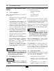
Table Of Contents
- New List
- Product & Safety Informatio
- Definitions
- Qualified Installer:
- Homeowner:
- Section I - Pre-Installation Items
- 1.2 Determining Product Location
- 1.3 Boiler Replacement
- 1.4 Recommended Clearances
- 1.5 Residential Garage Installations
- 1.6 Boiler Freeze Protection Feature
- SECTION II - Combustion Air and Venting
- 2.2 Ventilation and Combustion Air Requirements - Direct Vent
- 2.3 Ventilation and Combustion Air
- Requirements - Category IV
- 2.4 Methods of Accessing Combustion
- Air Into A Space - Category IV
- 2.4.1 Indoor Combustion Ai
- Opening Size and Location
- 2.4.2 Outdoor Combustion Ai
- Opening Size and Location
- 2.4.2.1 One Permanent Opening Method
- 2.4.2.2 Two Permanent Openings Method
- 2.4.3 Combination of Indoor and
- Outdoor Combustion Air
- 2.5 Combustion Air and Vent Piping
- 2.6 Removal of an Existing Boile
- from a Common Vent System
- 2.7 Commonwealth of Massachusetts Installations Only
- SECTION III - Unit Preparation
- 3.2 Wall Mounting Installation
- 3.3 Wall Mounting Guidelines
- 3.4 Stud Walls - Installation
- 3.4.1 PRESTIGE Solo 80/110/155/175/250
- 3.4.2 PRESTIGE Solo 299/399
- 3.5 Wall Bracket Installation - Solid Walls
- 3.6 Boiler Mounting
- SECTION IV - Boiler Pipin
- 4.2 Pressure Relief Valve
- 4.3 Boiler Air Vent
- 4.4 Low Water Cutoff Device
- 4.5 Additional Limit Control
- 4.6 Backflow Preventer
- 4.7 Boiler System Piping Applications
- 4.8 Expansion Tank and Makeup Water
- 4.8.1 Diaphragm Expansion Tank
- 4.8.2 Closed-Type Expansion Tank
- 4.9 Circulator
- 4.10 Sizing Primary Piping
- 4.11 Domestic Hot Water System Piping
- 4.12 System Piping - Zone Circulators
- 4.13 System Piping - Zone Valves
- 4.14 System Piping - Through Boiler
- 4.15 System Piping - Radiant Heating
- 4.16 System Piping - Special Application
- 4.17 System Piping - Multiple Units Installation
- SECTION V - Installing Vent / Combustion Air & Condensate Dra
- 5.1 Installing Vent and Combustion Air
- 5.2 Installing Condensate Drain Assembly
- SECTION VI - Gas Pipi
- 6.1 Gas Supply Piping Connection
- 6.2 Natural Gas
- 6.2.1 Pipe Sizing
- 6.2.2 Supply Pressure Requirements
- 6.3 Propane Gas
- 6.3.1 Pipe Sizing - Propane Gas
- 6.3.2 Propane Gas Supply Pressure Requirements
- SECTION VII - Internal Wiri
- SECTION VIII - External Wirin
- 8.2 Line Voltage Connections
- 8.3 Circulator Wiring
- 8.4 Alarm Wiring
- 8.5 Low Voltage Connections
- 8.6 Thermostat Wiring
- 8.7 Outdoor Sensor Wiring
- 8.8 Domestic Hot Water Wiring
- 8.9 Additional Boiler Limits
- 8.10 External Modulation Control
- 8.11 System Sensor Wiring
- 8.12 Cascade Wiring
- 8.13 Modbus Wiring
- SECTION IX - ACVMax Operatio
- 9.2 ACVMax Menu Structure
- 9.3 Home Screen
- 9.4 Status Line Messages
- 9.5 Main Menu
- 9.6 EZ Setup
- 9.7 Heating EZ Setup
- 9.7.1 Select CH Demand
- 9.7.2 CH1 Setpoint
- 9.7.3 CH2 Setpoint
- 9.7.4 Select CH1 Reset Curve
- 9.7.5 Select CH2 Reset Curve
- 9.7.6 Set Warm Weather Shutdown Temperature
- 9.7.7 CH EZ Setup Complete
- 9.8 Domestic Hot Water EZ Setup
- 9.8.1 Select DHW Demand
- 9.8.2 Boiler DHW Setpoint
- 9.8.3 DHW Storage Setpoint
- 9.8.4 DHW Priority Timeout
- 9.9 EZ Setup Reset
- 9.10 Display EZ Setup
- 9.11 CH/DHW Operation
- 9.12 Boiler Information
- 9.12.1 Boiler Information Logging
- 9.12.2 Information Items
- 9.13 Lockout History
- 9.13.1 Lockout Details
- 9.13.2 Lockout Screen
- SECTION X - Start-Up Preparatio
- 10.1.1 Boiler Fluid pH Level 6.0 to 8.0
- 10.1.2 Boiler Fluid Hardness Less Than 7 Grains
- 10.1.3 Chlorinated Water
- 10.1.4 Flush Boiler to Remove Sediment
- 10.1.5 Cleaning of Old Boiler/System:
- 10.1.6 Cleaning of New Boiler/System:
- 10.1.7 Check and Test Antifreeze
- 10.1.8 Use of Antifreeze in the Boiler System
- 10.2 Filling the Boiler System
- 10.3 Check Low Water Cut-Off Device
- 10.4 Check For Gas Leaks
- 10.6 Inspection of Condensate Drain Assembly
- SECTION XI - Start-Up Procedure
- 11.2 PRESTIGE Solo Start-Up
- 11.3 Check the PRESTIGE Solo and System
- SECTION XII - Outdoor Reset Contro
- 12.2 Wiring the Sensor
- SECTION XIII - External Modulating Contro
- 13.2 ACVMax Adjustment
- 13.3 Programming of External Modulating Control
- SECTION XV - Installation Recor
- 16.2 Owner Maintenance
- SECTION XVII- Maintenance Procedure
- 17.2 Reported Problems
- 17.3 Check Surrounding Area
- 17.4 Inspect Burner Area
- 17.5 Check System Piping
- 17.6 Clean Condensate Drain Assembly
- 17.7 Check Ventilation Air Openings
- 17.8 Inspect Vent and Combustion Air Piping
- 17.9 Check Boiler System
- 17.10 Check Expansion Tank
- 17.11 Check Boiler Relief Valve
- 17.12 Inspection of Ignitor
- 17.13 Check Ignition Wiring and Ground Wiring
- 17.14 Check Control Wiring
- 17.15 Check Control Settings
- 17.16 Perform Start-up and Checkout Procedures
- 17.17 Check Burner Flame
- 17.18 Check Flame Signal
- 17.19 Check Combustion Levels
- 17.20 Check Flue Gas Temperature
- 17.21 Clean Heat Exchanger
- 17.22 Review With Owner
- Section XVIII Replacement Part
- TC - Section 18
- PRESTIGE Solo 175/250 Jacket Components
- PRESTIGE Solo 299/399 Jacket Components
- PRESTIGE Solo 80/110 Internal Components
- PRESTIGE Solo 155/175/250 Internal Components
- PRESTIGE Solo 399 Internal Components
- PRESTIGE Solo 80/110 Burner Components
- PRESTIGE Solo 155/175/250 Burner Components
- PRESTIGE Solo 299/399 Burner Components
- PRESTIGE Solo Display Enclosure
- PRESTIGE Solo Control Enclosure
- New List
- TC - Section 19
- New List

Product & Safety Information
1
Indicates the presence of a hazardous
situation which, if ignored, will result in
death, serious injury or substantial
property damage.
Indicates a potentially hazardous situa-
tion which, if ignored, can result in
death, serious injury or substantial
property damage.
Indicates a potentially hazardous situa-
tion which, if ignored, may result in
minor injury or property damage.
Indicates special instructions on installa-
tion, operation or maintenance, which
are important to equipment but not
related to personal injury hazards.
Indicates recommendations made by
ACV-Triangle Tube for the installers
which will help to ensure optimum oper-
ation and longevity of the equipment
NOTICE
WARNING
CAUTION
BEST PRACTICE
DANGER
The following terms are used throughout this manual to bring attention to the presence of
potential hazards or important information concerning the product.
ACV-Triangle Tube reserves the right to modify the technical specifications and compo-
nents of its products without prior notice.
NOTICE
PRODUCT & SAFETY INFORMATION
Definitions