
Install Instructions


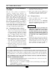
Table Of Contents
- New List
- Product & Safety Informatio
- Definitions
- Qualified Installer:
- Homeowner:
- Section I - Pre-Installation Items
- 1.2 Determining Product Location
- 1.3 Boiler Replacement
- 1.4 Recommended Clearances
- 1.5 Residential Garage Installations
- 1.6 Boiler Freeze Protection Feature
- SECTION II - Combustion Air and Venting
- 2.2 Ventilation and Combustion Air Requirements - Direct Vent
- 2.3 Ventilation and Combustion Air
- Requirements - Category IV
- 2.4 Methods of Accessing Combustion
- Air Into A Space - Category IV
- 2.4.1 Indoor Combustion Ai
- Opening Size and Location
- 2.4.2 Outdoor Combustion Ai
- Opening Size and Location
- 2.4.2.1 One Permanent Opening Method
- 2.4.2.2 Two Permanent Openings Method
- 2.4.3 Combination of Indoor and
- Outdoor Combustion Air
- 2.5 Combustion Air and Vent Piping
- 2.6 Removal of an Existing Boile
- from a Common Vent System
- 2.7 Commonwealth of Massachusetts Installations Only
- SECTION III - Unit Preparation
- 3.2 Wall Mounting Installation
- 3.3 Wall Mounting Guidelines
- 3.4 Stud Walls - Installation
- 3.4.1 PRESTIGE Solo 80/110/155/175/250
- 3.4.2 PRESTIGE Solo 299/399
- 3.5 Wall Bracket Installation - Solid Walls
- 3.6 Boiler Mounting
- SECTION IV - Boiler Pipin
- 4.2 Pressure Relief Valve
- 4.3 Boiler Air Vent
- 4.4 Low Water Cutoff Device
- 4.5 Additional Limit Control
- 4.6 Backflow Preventer
- 4.7 Boiler System Piping Applications
- 4.8 Expansion Tank and Makeup Water
- 4.8.1 Diaphragm Expansion Tank
- 4.8.2 Closed-Type Expansion Tank
- 4.9 Circulator
- 4.10 Sizing Primary Piping
- 4.11 Domestic Hot Water System Piping
- 4.12 System Piping - Zone Circulators
- 4.13 System Piping - Zone Valves
- 4.14 System Piping - Through Boiler
- 4.15 System Piping - Radiant Heating
- 4.16 System Piping - Special Application
- 4.17 System Piping - Multiple Units Installation
- SECTION V - Installing Vent / Combustion Air & Condensate Dra
- 5.1 Installing Vent and Combustion Air
- 5.2 Installing Condensate Drain Assembly
- SECTION VI - Gas Pipi
- 6.1 Gas Supply Piping Connection
- 6.2 Natural Gas
- 6.2.1 Pipe Sizing
- 6.2.2 Supply Pressure Requirements
- 6.3 Propane Gas
- 6.3.1 Pipe Sizing - Propane Gas
- 6.3.2 Propane Gas Supply Pressure Requirements
- SECTION VII - Internal Wiri
- SECTION VIII - External Wirin
- 8.2 Line Voltage Connections
- 8.3 Circulator Wiring
- 8.4 Alarm Wiring
- 8.5 Low Voltage Connections
- 8.6 Thermostat Wiring
- 8.7 Outdoor Sensor Wiring
- 8.8 Domestic Hot Water Wiring
- 8.9 Additional Boiler Limits
- 8.10 External Modulation Control
- 8.11 System Sensor Wiring
- 8.12 Cascade Wiring
- 8.13 Modbus Wiring
- SECTION IX - ACVMax Operatio
- 9.2 ACVMax Menu Structure
- 9.3 Home Screen
- 9.4 Status Line Messages
- 9.5 Main Menu
- 9.6 EZ Setup
- 9.7 Heating EZ Setup
- 9.7.1 Select CH Demand
- 9.7.2 CH1 Setpoint
- 9.7.3 CH2 Setpoint
- 9.7.4 Select CH1 Reset Curve
- 9.7.5 Select CH2 Reset Curve
- 9.7.6 Set Warm Weather Shutdown Temperature
- 9.7.7 CH EZ Setup Complete
- 9.8 Domestic Hot Water EZ Setup
- 9.8.1 Select DHW Demand
- 9.8.2 Boiler DHW Setpoint
- 9.8.3 DHW Storage Setpoint
- 9.8.4 DHW Priority Timeout
- 9.9 EZ Setup Reset
- 9.10 Display EZ Setup
- 9.11 CH/DHW Operation
- 9.12 Boiler Information
- 9.12.1 Boiler Information Logging
- 9.12.2 Information Items
- 9.13 Lockout History
- 9.13.1 Lockout Details
- 9.13.2 Lockout Screen
- SECTION X - Start-Up Preparatio
- 10.1.1 Boiler Fluid pH Level 6.0 to 8.0
- 10.1.2 Boiler Fluid Hardness Less Than 7 Grains
- 10.1.3 Chlorinated Water
- 10.1.4 Flush Boiler to Remove Sediment
- 10.1.5 Cleaning of Old Boiler/System:
- 10.1.6 Cleaning of New Boiler/System:
- 10.1.7 Check and Test Antifreeze
- 10.1.8 Use of Antifreeze in the Boiler System
- 10.2 Filling the Boiler System
- 10.3 Check Low Water Cut-Off Device
- 10.4 Check For Gas Leaks
- 10.6 Inspection of Condensate Drain Assembly
- SECTION XI - Start-Up Procedure
- 11.2 PRESTIGE Solo Start-Up
- 11.3 Check the PRESTIGE Solo and System
- SECTION XII - Outdoor Reset Contro
- 12.2 Wiring the Sensor
- SECTION XIII - External Modulating Contro
- 13.2 ACVMax Adjustment
- 13.3 Programming of External Modulating Control
- SECTION XV - Installation Recor
- 16.2 Owner Maintenance
- SECTION XVII- Maintenance Procedure
- 17.2 Reported Problems
- 17.3 Check Surrounding Area
- 17.4 Inspect Burner Area
- 17.5 Check System Piping
- 17.6 Clean Condensate Drain Assembly
- 17.7 Check Ventilation Air Openings
- 17.8 Inspect Vent and Combustion Air Piping
- 17.9 Check Boiler System
- 17.10 Check Expansion Tank
- 17.11 Check Boiler Relief Valve
- 17.12 Inspection of Ignitor
- 17.13 Check Ignition Wiring and Ground Wiring
- 17.14 Check Control Wiring
- 17.15 Check Control Settings
- 17.16 Perform Start-up and Checkout Procedures
- 17.17 Check Burner Flame
- 17.18 Check Flame Signal
- 17.19 Check Combustion Levels
- 17.20 Check Flue Gas Temperature
- 17.21 Clean Heat Exchanger
- 17.22 Review With Owner
- Section XVIII Replacement Part
- TC - Section 18
- PRESTIGE Solo 175/250 Jacket Components
- PRESTIGE Solo 299/399 Jacket Components
- PRESTIGE Solo 80/110 Internal Components
- PRESTIGE Solo 155/175/250 Internal Components
- PRESTIGE Solo 399 Internal Components
- PRESTIGE Solo 80/110 Burner Components
- PRESTIGE Solo 155/175/250 Burner Components
- PRESTIGE Solo 299/399 Burner Components
- PRESTIGE Solo Display Enclosure
- PRESTIGE Solo Control Enclosure
- New List
- TC - Section 19
- New List

60
11.0 Start-Up Procedures
c Check Vent Piping and Combustion Air
Piping.
Check for gas-tight seal at every con-
nection and seam of the venting and
combustion air piping.
Venting system must be sealed gas-tight
to prevent flue gas spillage and potential
carbon monoxide emissions, which will
result in severe personal injury or death.
c Check Gas Piping
Check around the unit for gas odor fol-
lowing the procedure outlined in this
manual on Page 63.
If any gas leaks are found or suspected,
shut the unit down immediately. Use a
gas detection device or bubble test to
locate the source of the gas leak and
repair at once. Do not operate the unit
until the leak is corrected. Failure to
comply with this procedure could result
in severe personal injury, death or sub-
stantial property damage.
c Verify Flame Pattern and Combustion
1. Check the flame pattern through the
inspection port of the heat exchanger.
The flame should be blue and stable.
The flame should be the length of the
burner head openings.
The combustion testing and adjustments
must be performed by a qualified
installer, service agency or the gas suppli-
er. All combustion measurements must
be performed with calibrated equipment
to ensure proper reading and accuracy.
2. Test for CO2 or O2 and for CO during
high firing rate. The combustion read-
ings should be within the range listed in
Table 4 on page 61. The CO level
should not exceed 100 ppm when
combustion is correct. Perform the
following procedure to manually place
the burner into high fire.
a. Press the round INSTALLER button.
Reference Fig. 30, page 41.
b. Enter the installer access code “054” by
using the LEFT and RIGHT buttons to
select a digit and the UP and DOWN
buttons to change the digit. Press the
OK button to enter the access code.
c. Press the RIGHT button to highlight
the Manual Operation icon then
press the OK button.
d. Press the OK button while the FAN
icon is highlighted to manually fire the
burner and power the CH circulator.
An adequate CH load must be present to
dissipate the heat generated during the
combustion test. If an adequate CH load
is not available, an indirect water heater
can be used to dissipate the heat by cre-
ating a DHW call which will enable the
DHW circulator.
WARNING
WARNING
WARNING
NOTICE
Manual Operation
Released
O
O
O
CH1
FAN
DHW
CH2