
Install Instructions
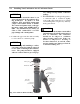
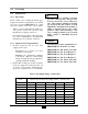
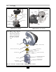
Table Of Contents
- New List
- Product & Safety Informatio
- Definitions
- Qualified Installer:
- Homeowner:
- Section I - Pre-Installation Items
- 1.2 Determining Product Location
- 1.3 Boiler Replacement
- 1.4 Recommended Clearances
- 1.5 Residential Garage Installations
- 1.6 Boiler Freeze Protection Feature
- SECTION II - Combustion Air and Venting
- 2.2 Ventilation and Combustion Air Requirements - Direct Vent
- 2.3 Ventilation and Combustion Air
- Requirements - Category IV
- 2.4 Methods of Accessing Combustion
- Air Into A Space - Category IV
- 2.4.1 Indoor Combustion Ai
- Opening Size and Location
- 2.4.2 Outdoor Combustion Ai
- Opening Size and Location
- 2.4.2.1 One Permanent Opening Method
- 2.4.2.2 Two Permanent Openings Method
- 2.4.3 Combination of Indoor and
- Outdoor Combustion Air
- 2.5 Combustion Air and Vent Piping
- 2.6 Removal of an Existing Boile
- from a Common Vent System
- 2.7 Commonwealth of Massachusetts Installations Only
- SECTION III - Unit Preparation
- 3.2 Wall Mounting Installation
- 3.3 Wall Mounting Guidelines
- 3.4 Stud Walls - Installation
- 3.4.1 PRESTIGE Solo 80/110/155/175/250
- 3.4.2 PRESTIGE Solo 299/399
- 3.5 Wall Bracket Installation - Solid Walls
- 3.6 Boiler Mounting
- SECTION IV - Boiler Pipin
- 4.2 Pressure Relief Valve
- 4.3 Boiler Air Vent
- 4.4 Low Water Cutoff Device
- 4.5 Additional Limit Control
- 4.6 Backflow Preventer
- 4.7 Boiler System Piping Applications
- 4.8 Expansion Tank and Makeup Water
- 4.8.1 Diaphragm Expansion Tank
- 4.8.2 Closed-Type Expansion Tank
- 4.9 Circulator
- 4.10 Sizing Primary Piping
- 4.11 Domestic Hot Water System Piping
- 4.12 System Piping - Zone Circulators
- 4.13 System Piping - Zone Valves
- 4.14 System Piping - Through Boiler
- 4.15 System Piping - Radiant Heating
- 4.16 System Piping - Special Application
- 4.17 System Piping - Multiple Units Installation
- SECTION V - Installing Vent / Combustion Air & Condensate Dra
- 5.1 Installing Vent and Combustion Air
- 5.2 Installing Condensate Drain Assembly
- SECTION VI - Gas Pipi
- 6.1 Gas Supply Piping Connection
- 6.2 Natural Gas
- 6.2.1 Pipe Sizing
- 6.2.2 Supply Pressure Requirements
- 6.3 Propane Gas
- 6.3.1 Pipe Sizing - Propane Gas
- 6.3.2 Propane Gas Supply Pressure Requirements
- SECTION VII - Internal Wiri
- SECTION VIII - External Wirin
- 8.2 Line Voltage Connections
- 8.3 Circulator Wiring
- 8.4 Alarm Wiring
- 8.5 Low Voltage Connections
- 8.6 Thermostat Wiring
- 8.7 Outdoor Sensor Wiring
- 8.8 Domestic Hot Water Wiring
- 8.9 Additional Boiler Limits
- 8.10 External Modulation Control
- 8.11 System Sensor Wiring
- 8.12 Cascade Wiring
- 8.13 Modbus Wiring
- SECTION IX - ACVMax Operatio
- 9.2 ACVMax Menu Structure
- 9.3 Home Screen
- 9.4 Status Line Messages
- 9.5 Main Menu
- 9.6 EZ Setup
- 9.7 Heating EZ Setup
- 9.7.1 Select CH Demand
- 9.7.2 CH1 Setpoint
- 9.7.3 CH2 Setpoint
- 9.7.4 Select CH1 Reset Curve
- 9.7.5 Select CH2 Reset Curve
- 9.7.6 Set Warm Weather Shutdown Temperature
- 9.7.7 CH EZ Setup Complete
- 9.8 Domestic Hot Water EZ Setup
- 9.8.1 Select DHW Demand
- 9.8.2 Boiler DHW Setpoint
- 9.8.3 DHW Storage Setpoint
- 9.8.4 DHW Priority Timeout
- 9.9 EZ Setup Reset
- 9.10 Display EZ Setup
- 9.11 CH/DHW Operation
- 9.12 Boiler Information
- 9.12.1 Boiler Information Logging
- 9.12.2 Information Items
- 9.13 Lockout History
- 9.13.1 Lockout Details
- 9.13.2 Lockout Screen
- SECTION X - Start-Up Preparatio
- 10.1.1 Boiler Fluid pH Level 6.0 to 8.0
- 10.1.2 Boiler Fluid Hardness Less Than 7 Grains
- 10.1.3 Chlorinated Water
- 10.1.4 Flush Boiler to Remove Sediment
- 10.1.5 Cleaning of Old Boiler/System:
- 10.1.6 Cleaning of New Boiler/System:
- 10.1.7 Check and Test Antifreeze
- 10.1.8 Use of Antifreeze in the Boiler System
- 10.2 Filling the Boiler System
- 10.3 Check Low Water Cut-Off Device
- 10.4 Check For Gas Leaks
- 10.6 Inspection of Condensate Drain Assembly
- SECTION XI - Start-Up Procedure
- 11.2 PRESTIGE Solo Start-Up
- 11.3 Check the PRESTIGE Solo and System
- SECTION XII - Outdoor Reset Contro
- 12.2 Wiring the Sensor
- SECTION XIII - External Modulating Contro
- 13.2 ACVMax Adjustment
- 13.3 Programming of External Modulating Control
- SECTION XV - Installation Recor
- 16.2 Owner Maintenance
- SECTION XVII- Maintenance Procedure
- 17.2 Reported Problems
- 17.3 Check Surrounding Area
- 17.4 Inspect Burner Area
- 17.5 Check System Piping
- 17.6 Clean Condensate Drain Assembly
- 17.7 Check Ventilation Air Openings
- 17.8 Inspect Vent and Combustion Air Piping
- 17.9 Check Boiler System
- 17.10 Check Expansion Tank
- 17.11 Check Boiler Relief Valve
- 17.12 Inspection of Ignitor
- 17.13 Check Ignition Wiring and Ground Wiring
- 17.14 Check Control Wiring
- 17.15 Check Control Settings
- 17.16 Perform Start-up and Checkout Procedures
- 17.17 Check Burner Flame
- 17.18 Check Flame Signal
- 17.19 Check Combustion Levels
- 17.20 Check Flue Gas Temperature
- 17.21 Clean Heat Exchanger
- 17.22 Review With Owner
- Section XVIII Replacement Part
- TC - Section 18
- PRESTIGE Solo 175/250 Jacket Components
- PRESTIGE Solo 299/399 Jacket Components
- PRESTIGE Solo 80/110 Internal Components
- PRESTIGE Solo 155/175/250 Internal Components
- PRESTIGE Solo 399 Internal Components
- PRESTIGE Solo 80/110 Burner Components
- PRESTIGE Solo 155/175/250 Burner Components
- PRESTIGE Solo 299/399 Burner Components
- PRESTIGE Solo Display Enclosure
- PRESTIGE Solo Control Enclosure
- New List
- TC - Section 19
- New List

28
6.0 Gas Piping
6.3 Propane Gas
6.3.1 Pipe Sizing - Propane Gas
The unit was shipped with a propane
conversion kit which is located on the
top of the unit in the instructions packet.
This kit includes all the necessary parts
and instruction to perform the conver-
sion from natural to propane gas. If this
conversion kit is missing, please contact
ACV-Triangle Tube Technical Support
before installing unit for missing kit.
Prior to start up, ensure the unit is set to
fire propane. Check the rating label for
the type of fuel. Check the gas valve for
propane conversion label. If there is a
conflict or doubt on the burner set up,
remove the gas valve and check for the
propane orifice, see Fig. 16, 17 or 18 on
page 29. Failure to ensure proper burner
setup could result in severe personal
injury, death or substantial property
damage.
Contact the local propane gas supplier for rec-
ommended sizing of piping, tanks and 100%
lockup gas regulator.
6.3.2 Propane Gas Supply Pressure
Requirements
1. Adjust the propane supply regulator pro-
vided by the gas supplier for 13”w.c. max-
imum pressure
2. Pressure required at the gas valve inlet sup-
ply pressure port:
- Maximum 13”w.c. at flow or no flow
conditions to the burner
- Minimum 5”w.c. during flow conditions
to the burner. Must be verified during
start up and with all other gas appliances
operating within the building.
DO NOT adjust or attempt to measure
gas valve outlet pressure. The gas valve
is factory-set for the correct outlet pres-
sure. This setting is suitable for natural
gas and propane and requires no field
adjustment. Attempts by the installer to
adjust or measure the gas valve outlet
pressure could result in damage to the
valve, causing potential severe personal
injury, death or substantial property
damage.
The propane orifice requirements are:
PRESTIGE Solo 80: 0.142” (3.6 mm)
PRESTIGE Solo 110: 0.185” (4.7 mm)
PRESTIGE Solo 155: 0.205” (5.2 mm)
PRESTIGE Solo 175: 0.236” (6.0 mm)
PRESTIGE Solo 250: 0.268” (6.8 mm)
PRESTIGE Solo 299: 0.339” (8.6 mm)
PRESTIGE Solo 399: 0.339” (8.6 mm)
WARNING
NOTICE
WARNING
WARNING