
Install Instructions
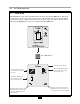
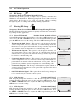
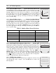
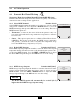
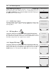
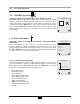
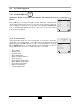
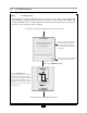
Table Of Contents
- New List
- Product & Safety Informatio
- Definitions
- Qualified Installer:
- Homeowner:
- Section I - Pre-Installation Items
- 1.2 Determining Product Location
- 1.3 Boiler Replacement
- 1.4 Recommended Clearances
- 1.5 Residential Garage Installations
- 1.6 Boiler Freeze Protection Feature
- SECTION II - Combustion Air and Venting
- 2.2 Ventilation and Combustion Air Requirements - Direct Vent
- 2.3 Ventilation and Combustion Air
- Requirements - Category IV
- 2.4 Methods of Accessing Combustion
- Air Into A Space - Category IV
- 2.4.1 Indoor Combustion Ai
- Opening Size and Location
- 2.4.2 Outdoor Combustion Ai
- Opening Size and Location
- 2.4.2.1 One Permanent Opening Method
- 2.4.2.2 Two Permanent Openings Method
- 2.4.3 Combination of Indoor and
- Outdoor Combustion Air
- 2.5 Combustion Air and Vent Piping
- 2.6 Removal of an Existing Boile
- from a Common Vent System
- 2.7 Commonwealth of Massachusetts Installations Only
- SECTION III - Unit Preparation
- 3.2 Wall Mounting Installation
- 3.3 Wall Mounting Guidelines
- 3.4 Stud Walls - Installation
- 3.4.1 PRESTIGE Solo 80/110/155/175/250
- 3.4.2 PRESTIGE Solo 299/399
- 3.5 Wall Bracket Installation - Solid Walls
- 3.6 Boiler Mounting
- SECTION IV - Boiler Pipin
- 4.2 Pressure Relief Valve
- 4.3 Boiler Air Vent
- 4.4 Low Water Cutoff Device
- 4.5 Additional Limit Control
- 4.6 Backflow Preventer
- 4.7 Boiler System Piping Applications
- 4.8 Expansion Tank and Makeup Water
- 4.8.1 Diaphragm Expansion Tank
- 4.8.2 Closed-Type Expansion Tank
- 4.9 Circulator
- 4.10 Sizing Primary Piping
- 4.11 Domestic Hot Water System Piping
- 4.12 System Piping - Zone Circulators
- 4.13 System Piping - Zone Valves
- 4.14 System Piping - Through Boiler
- 4.15 System Piping - Radiant Heating
- 4.16 System Piping - Special Application
- 4.17 System Piping - Multiple Units Installation
- SECTION V - Installing Vent / Combustion Air & Condensate Dra
- 5.1 Installing Vent and Combustion Air
- 5.2 Installing Condensate Drain Assembly
- SECTION VI - Gas Pipi
- 6.1 Gas Supply Piping Connection
- 6.2 Natural Gas
- 6.2.1 Pipe Sizing
- 6.2.2 Supply Pressure Requirements
- 6.3 Propane Gas
- 6.3.1 Pipe Sizing - Propane Gas
- 6.3.2 Propane Gas Supply Pressure Requirements
- SECTION VII - Internal Wiri
- SECTION VIII - External Wirin
- 8.2 Line Voltage Connections
- 8.3 Circulator Wiring
- 8.4 Alarm Wiring
- 8.5 Low Voltage Connections
- 8.6 Thermostat Wiring
- 8.7 Outdoor Sensor Wiring
- 8.8 Domestic Hot Water Wiring
- 8.9 Additional Boiler Limits
- 8.10 External Modulation Control
- 8.11 System Sensor Wiring
- 8.12 Cascade Wiring
- 8.13 Modbus Wiring
- SECTION IX - ACVMax Operatio
- 9.2 ACVMax Menu Structure
- 9.3 Home Screen
- 9.4 Status Line Messages
- 9.5 Main Menu
- 9.6 EZ Setup
- 9.7 Heating EZ Setup
- 9.7.1 Select CH Demand
- 9.7.2 CH1 Setpoint
- 9.7.3 CH2 Setpoint
- 9.7.4 Select CH1 Reset Curve
- 9.7.5 Select CH2 Reset Curve
- 9.7.6 Set Warm Weather Shutdown Temperature
- 9.7.7 CH EZ Setup Complete
- 9.8 Domestic Hot Water EZ Setup
- 9.8.1 Select DHW Demand
- 9.8.2 Boiler DHW Setpoint
- 9.8.3 DHW Storage Setpoint
- 9.8.4 DHW Priority Timeout
- 9.9 EZ Setup Reset
- 9.10 Display EZ Setup
- 9.11 CH/DHW Operation
- 9.12 Boiler Information
- 9.12.1 Boiler Information Logging
- 9.12.2 Information Items
- 9.13 Lockout History
- 9.13.1 Lockout Details
- 9.13.2 Lockout Screen
- SECTION X - Start-Up Preparatio
- 10.1.1 Boiler Fluid pH Level 6.0 to 8.0
- 10.1.2 Boiler Fluid Hardness Less Than 7 Grains
- 10.1.3 Chlorinated Water
- 10.1.4 Flush Boiler to Remove Sediment
- 10.1.5 Cleaning of Old Boiler/System:
- 10.1.6 Cleaning of New Boiler/System:
- 10.1.7 Check and Test Antifreeze
- 10.1.8 Use of Antifreeze in the Boiler System
- 10.2 Filling the Boiler System
- 10.3 Check Low Water Cut-Off Device
- 10.4 Check For Gas Leaks
- 10.6 Inspection of Condensate Drain Assembly
- SECTION XI - Start-Up Procedure
- 11.2 PRESTIGE Solo Start-Up
- 11.3 Check the PRESTIGE Solo and System
- SECTION XII - Outdoor Reset Contro
- 12.2 Wiring the Sensor
- SECTION XIII - External Modulating Contro
- 13.2 ACVMax Adjustment
- 13.3 Programming of External Modulating Control
- SECTION XV - Installation Recor
- 16.2 Owner Maintenance
- SECTION XVII- Maintenance Procedure
- 17.2 Reported Problems
- 17.3 Check Surrounding Area
- 17.4 Inspect Burner Area
- 17.5 Check System Piping
- 17.6 Clean Condensate Drain Assembly
- 17.7 Check Ventilation Air Openings
- 17.8 Inspect Vent and Combustion Air Piping
- 17.9 Check Boiler System
- 17.10 Check Expansion Tank
- 17.11 Check Boiler Relief Valve
- 17.12 Inspection of Ignitor
- 17.13 Check Ignition Wiring and Ground Wiring
- 17.14 Check Control Wiring
- 17.15 Check Control Settings
- 17.16 Perform Start-up and Checkout Procedures
- 17.17 Check Burner Flame
- 17.18 Check Flame Signal
- 17.19 Check Combustion Levels
- 17.20 Check Flue Gas Temperature
- 17.21 Clean Heat Exchanger
- 17.22 Review With Owner
- Section XVIII Replacement Part
- TC - Section 18
- PRESTIGE Solo 175/250 Jacket Components
- PRESTIGE Solo 299/399 Jacket Components
- PRESTIGE Solo 80/110 Internal Components
- PRESTIGE Solo 155/175/250 Internal Components
- PRESTIGE Solo 399 Internal Components
- PRESTIGE Solo 80/110 Burner Components
- PRESTIGE Solo 155/175/250 Burner Components
- PRESTIGE Solo 299/399 Burner Components
- PRESTIGE Solo Display Enclosure
- PRESTIGE Solo Control Enclosure
- New List
- TC - Section 19
- New List

48
9.0 ACVMax Operation
Navigation: Home Screen>Main Menu>EZ Setup>DHW EZ Setup
Domestic Hot Water EZ Setup allows the installer to quickly customize the
domestic hot water settings for the application.
9.8.1 Select DHW Demand Default: Switch
Select DHW Demand prompts the installer to select the type of device which
will generate a DHW call. Press the UP or DOWN buttons to select the
DHW Demand type then press the OK button to store the setting. The Select
DHW Demand options are:
• Thermostat – A domestic hot water call from an aquastat or dry con-
tact switch will enable the Prestige with a fixed setpoint for a domestic
hot water call.
• Sensor – This option requires the use of Indirect Water Heater Sensor
PSRKIT22. The Prestige will monitor the DHW storage temperature
and generate a domestic hot water call when the temperature drops
below the DHW Storage Setpoint by 6ºF [3ºC].
9.8.2 Boiler DHW Setpoint Default: 186°F [86°C]
Boiler DHW Setpoint prompts the installer to enter the fixed boiler setpoint
temperature during a Domestic hot water call when the Switch option is cho-
sen in Select DHW Demand. Press the LEFT or RIGHT buttons to adjust
the Boiler DHW Setpoint then press the OK button to store the setting.
9.8.3 DHW Storage Setpoint Default: 140°F [60°C]
DHW Storage Setpoint prompts the installer to enter the domestic hot water
storage setpoint temperature when the Sensor option is chosen in Select
DHW Demand. Press the LEFT or RIGHT buttons to adjust the DHW
Storage Setpoint then press the OK button to store the setting.
The Boiler DHW Setpoint will automatically be set 46°F [25°C]
higher than the DHW Storage Setpoint setting.
NOTICE
9.8 Domestic Hot Water EZ Setup
S
elect DHW Demand
Thermostat
S
ensor
96ºF
188ºF
186ºF
Boiler
DHW Setpoint
68ºF
150ºF
140ºF
DHW
Storage Setpoint