
Install Instructions

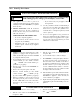
Table Of Contents
- New List
- Product & Safety Informatio
- Definitions
- Qualified Installer:
- Homeowner:
- Section I - Pre-Installation Items
- 1.2 Determining Product Location
- 1.3 Boiler Replacement
- 1.4 Recommended Clearances
- 1.5 Residential Garage Installations
- 1.6 Boiler Freeze Protection Feature
- SECTION II - Combustion Air and Venting
- 2.2 Ventilation and Combustion Air Requirements - Direct Vent
- 2.3 Ventilation and Combustion Air
- Requirements - Category IV
- 2.4 Methods of Accessing Combustion
- Air Into A Space - Category IV
- 2.4.1 Indoor Combustion Ai
- Opening Size and Location
- 2.4.2 Outdoor Combustion Ai
- Opening Size and Location
- 2.4.2.1 One Permanent Opening Method
- 2.4.2.2 Two Permanent Openings Method
- 2.4.3 Combination of Indoor and
- Outdoor Combustion Air
- 2.5 Combustion Air and Vent Piping
- 2.6 Removal of an Existing Boile
- from a Common Vent System
- 2.7 Commonwealth of Massachusetts Installations Only
- SECTION III - Unit Preparation
- 3.2 Wall Mounting Installation
- 3.3 Wall Mounting Guidelines
- 3.4 Stud Walls - Installation
- 3.4.1 PRESTIGE Solo 80/110/155/175/250
- 3.4.2 PRESTIGE Solo 299/399
- 3.5 Wall Bracket Installation - Solid Walls
- 3.6 Boiler Mounting
- SECTION IV - Boiler Pipin
- 4.2 Pressure Relief Valve
- 4.3 Boiler Air Vent
- 4.4 Low Water Cutoff Device
- 4.5 Additional Limit Control
- 4.6 Backflow Preventer
- 4.7 Boiler System Piping Applications
- 4.8 Expansion Tank and Makeup Water
- 4.8.1 Diaphragm Expansion Tank
- 4.8.2 Closed-Type Expansion Tank
- 4.9 Circulator
- 4.10 Sizing Primary Piping
- 4.11 Domestic Hot Water System Piping
- 4.12 System Piping - Zone Circulators
- 4.13 System Piping - Zone Valves
- 4.14 System Piping - Through Boiler
- 4.15 System Piping - Radiant Heating
- 4.16 System Piping - Special Application
- 4.17 System Piping - Multiple Units Installation
- SECTION V - Installing Vent / Combustion Air & Condensate Dra
- 5.1 Installing Vent and Combustion Air
- 5.2 Installing Condensate Drain Assembly
- SECTION VI - Gas Pipi
- 6.1 Gas Supply Piping Connection
- 6.2 Natural Gas
- 6.2.1 Pipe Sizing
- 6.2.2 Supply Pressure Requirements
- 6.3 Propane Gas
- 6.3.1 Pipe Sizing - Propane Gas
- 6.3.2 Propane Gas Supply Pressure Requirements
- SECTION VII - Internal Wiri
- SECTION VIII - External Wirin
- 8.2 Line Voltage Connections
- 8.3 Circulator Wiring
- 8.4 Alarm Wiring
- 8.5 Low Voltage Connections
- 8.6 Thermostat Wiring
- 8.7 Outdoor Sensor Wiring
- 8.8 Domestic Hot Water Wiring
- 8.9 Additional Boiler Limits
- 8.10 External Modulation Control
- 8.11 System Sensor Wiring
- 8.12 Cascade Wiring
- 8.13 Modbus Wiring
- SECTION IX - ACVMax Operatio
- 9.2 ACVMax Menu Structure
- 9.3 Home Screen
- 9.4 Status Line Messages
- 9.5 Main Menu
- 9.6 EZ Setup
- 9.7 Heating EZ Setup
- 9.7.1 Select CH Demand
- 9.7.2 CH1 Setpoint
- 9.7.3 CH2 Setpoint
- 9.7.4 Select CH1 Reset Curve
- 9.7.5 Select CH2 Reset Curve
- 9.7.6 Set Warm Weather Shutdown Temperature
- 9.7.7 CH EZ Setup Complete
- 9.8 Domestic Hot Water EZ Setup
- 9.8.1 Select DHW Demand
- 9.8.2 Boiler DHW Setpoint
- 9.8.3 DHW Storage Setpoint
- 9.8.4 DHW Priority Timeout
- 9.9 EZ Setup Reset
- 9.10 Display EZ Setup
- 9.11 CH/DHW Operation
- 9.12 Boiler Information
- 9.12.1 Boiler Information Logging
- 9.12.2 Information Items
- 9.13 Lockout History
- 9.13.1 Lockout Details
- 9.13.2 Lockout Screen
- SECTION X - Start-Up Preparatio
- 10.1.1 Boiler Fluid pH Level 6.0 to 8.0
- 10.1.2 Boiler Fluid Hardness Less Than 7 Grains
- 10.1.3 Chlorinated Water
- 10.1.4 Flush Boiler to Remove Sediment
- 10.1.5 Cleaning of Old Boiler/System:
- 10.1.6 Cleaning of New Boiler/System:
- 10.1.7 Check and Test Antifreeze
- 10.1.8 Use of Antifreeze in the Boiler System
- 10.2 Filling the Boiler System
- 10.3 Check Low Water Cut-Off Device
- 10.4 Check For Gas Leaks
- 10.6 Inspection of Condensate Drain Assembly
- SECTION XI - Start-Up Procedure
- 11.2 PRESTIGE Solo Start-Up
- 11.3 Check the PRESTIGE Solo and System
- SECTION XII - Outdoor Reset Contro
- 12.2 Wiring the Sensor
- SECTION XIII - External Modulating Contro
- 13.2 ACVMax Adjustment
- 13.3 Programming of External Modulating Control
- SECTION XV - Installation Recor
- 16.2 Owner Maintenance
- SECTION XVII- Maintenance Procedure
- 17.2 Reported Problems
- 17.3 Check Surrounding Area
- 17.4 Inspect Burner Area
- 17.5 Check System Piping
- 17.6 Clean Condensate Drain Assembly
- 17.7 Check Ventilation Air Openings
- 17.8 Inspect Vent and Combustion Air Piping
- 17.9 Check Boiler System
- 17.10 Check Expansion Tank
- 17.11 Check Boiler Relief Valve
- 17.12 Inspection of Ignitor
- 17.13 Check Ignition Wiring and Ground Wiring
- 17.14 Check Control Wiring
- 17.15 Check Control Settings
- 17.16 Perform Start-up and Checkout Procedures
- 17.17 Check Burner Flame
- 17.18 Check Flame Signal
- 17.19 Check Combustion Levels
- 17.20 Check Flue Gas Temperature
- 17.21 Clean Heat Exchanger
- 17.22 Review With Owner
- Section XVIII Replacement Part
- TC - Section 18
- PRESTIGE Solo 175/250 Jacket Components
- PRESTIGE Solo 299/399 Jacket Components
- PRESTIGE Solo 80/110 Internal Components
- PRESTIGE Solo 155/175/250 Internal Components
- PRESTIGE Solo 399 Internal Components
- PRESTIGE Solo 80/110 Burner Components
- PRESTIGE Solo 155/175/250 Burner Components
- PRESTIGE Solo 299/399 Burner Components
- PRESTIGE Solo Display Enclosure
- PRESTIGE Solo Control Enclosure
- New List
- TC - Section 19
- New List

64
12.0 Outdoor Reset Control
SECTION XII - OUTDOOR RESET
CONTROL
The use of the outdoor reset function is
required to optimize boiler efficiency, see
notice below. If the outdoor sensor is not
installed before turning on the boiler, an
Outdoor Sensor Open error (E96) will be dis-
played. The error will not prevent the boiler
from operating. The error will automatically
reset once the outdoor sensor is installed or if
the outdoor reset function is disabled.
Reference ACVMax Operation - EZ Setup sec-
tion for information on disabling the outdoor
reset function. The outdoor reset function can
only be disabled if the boiler installation meets
one of the exceptions listed in the notice.
12.1 Mounting the Outdoor Sensor
1. The exterior wall selected for mounting the
outdoor sensor should represent the heat
load of the building. Typically a northern
or northeastern wall will suit most build-
ings. A southern facing wall for those
buildings, which may have large glass
walls or windows on the southern face.
2. Ensure the outdoor sensor is shielded from
direct sunlight or the effects of heat or cold
from other sources (exhaust fans, appliance
vents...) to prevent false temperature sensing.
3. Mount the outdoor sensor at an elevation
on the exterior wall to prevent accidental
damage or tampering.
4. Avoid mounting the outdoor sensor in areas
subjected to excessive moisture.
5. Once an area on the exterior wall has been
determined, follow the mounting instruc-
tions included with the outdoor sensor.
12.2 Wiring the Sensor
1. Connect 18 AWG 2-wire cable or similar
cable to the outdoor sensor.
2. Route the cable back to the PRESTIGE
Solo boiler, ensuring the wires are not run
parallel to telephone or power cables.
If the sensor wires are located in an area
with sources of potential electromagnetic
interference (EMI) the sensor wires
should be shielded or the wires should be
routed in a grounded metal conduit. If
using shielded cable, the shielding should
be connected to the common ground of
the unit.
3. Connect the outdoor sensor wires to the out-
door sensor terminals on the low voltage ter-
minal strip located on the boiler control
module inside the enclosure (see Fig. 20 on
page 31 and Fig. 22 on page 33). The out-
door sensor wires do not have polarity.
NOTICE
IMPORTANT
In accordance with Section 325 (f) (3) of the Energy Policy and Conservation Act, this boil-
er is equipped with a feature that saves energy by reducing the boiler water temperature as the
heating load decreases. This feature is equipped with an override which is provided primari-
ly to permit the use of an external energy management system that serves the same function.
THIS OVERRIDE MUST NOT BE USED UNLESS AT LEAST ONE OF THE FOL-
LOWING CONDITIONS IS TRUE.
• An external energy management system is installed that reduces the boiler water tem-
perature as the heating load decreases.
• This boiler is not used for any space heating
• This boiler is part of a modular or multiple boiler system having a total input of
300,000 BTU/hr or greater.
• This boiler is equipped with a tankless coil.