
Full Product Manual


4.0 Boiler Piping
SECTION IV - BOILER PIPING
4.1 General Piping Requirements
- All plumbing must meet or exceed all local,
state and national plumbing codes.
- Support all piping using hangers. DO NOT
support piping by the unit or its components.
- Use isolation valves to isolate system com-
ponents.
- Install unions for easy removal of the
PRESTIGE Excellence from the system
piping.
Use a two wrench method when tighten-
ing piping onto the boiler connections.
Use one wrench to prevent the boiler
piping from turning / twisting. Failure
to support the boiler piping and connec-
tions in this manner could cause damage
to the boiler and its components.
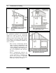
4.2 Pressure Relief Valve
1. The PRESTIGE Excellence is supplied
with a 30 psi pressure relief valve and must
be piped using the PRV connection as
shown in Fig. 5 page 15.
2. To avoid potential water damage to the sur-
rounding area or potential scalding hazard
due to the operation of the relief valve, the
discharge piping:
- Must be connected to the discharge out-
let of the relief valve and directed to a
safe place of disposal.
- Length should be as short and direct as
possible. The size of the discharge line
should not be reduced, maintain the
same size as the outlet of the relief valve.
- Should be directed downward towards
the floor at all times. The piping should
terminate at least 6 inches [153 mm]
above any drain connection to allow
clear visibility of the discharge.
- Should terminate with a plain end, not
with a threaded end. The material of
the piping should have a serviceable
temperature rating of 250ºF or greater.
- Should not be subject to conditions
where freezing could occur.
- Should not contain any shut-off valves
or obstructions. No shut-off valve
should be piped between the boiler and
relief valve.
Failure to comply with the guidelines on
installing the pressure relief valve and
discharge piping can result in personal
injury, death or substantial property
damage.
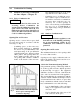
4.3 Boiler Air Vent
This boiler is supplied with a special
automatic air vent that will provide reli-
able operation in purging air from the
boiler. The hygroscopic cap supplied
with the automatic air vent MUST
remain tight at all times on the air vent
body. The hygroscopic cap has a mem-
brane which expands upon contact with
water and seals the air vent until the
membrane dries up due to new air form-
ing in the air vent.
1. Make sure to fully tighten the cap on the air
vent on initial installation.
2. Never loosen the hygroscopic cap to allow
air to escape the air vent. Air will exit with
the cap fully tightened in place.
3. If the hygroscopic cap is not fully tight-
ened, water may leak from the cap. Simply
tighten the cap securely.
NOTICE
WARNING
WARNING
14