prestige Excellence Water Boiler Part 1 of 2 (Part 2 begins on page 82) LI STED * I N S TALLAT I O N AN D MAI N T E NAN C E * M A N U A L NOTICE Warranty Registration Card must be filled out by the customer and mailed within thirty (30) days of installation in order to gain warranty coverage. When receiving the PRESTIGE Excellence unit, any claims for damage or shortage in shipment must be filed immediately against the transportation company by the consignee.
WARNING This manual outlines the requirements for installation of the PRESTIGE Excellence. Those requirements include Boiler Piping, Venting/Combustion Air, Start-Up and Maintenance. - For detailed instructions regarding the installation of the vent/combustion air system reference the PRESTIGE Vent Supplement and/or the various optional vent kit instructions.
Table of Contents PRODUCT AND SAFETY INFORMATION Definitions. . . . . . . . . . . . . . . . . . . . . . . . . . . . . . . . . . . . . . . . . . . . . . . . . . . 1 Product and Safety Information . . . . . . . . . . . . . . . . . . . . . . . . . . . . . . . . . . 2 SECTION I - PRE-INSTALLATION ITEMS Code Compliance . . . . . . . . . . . . . . . . . . . . . . . . . . . . . . . . . . . . . . . . . . . . . 3 Determining Product Location . . . . . . . . . . . . . . . . . . . . . . . . . . . . . . . . . . .
Table of Contents Backflow Preventer. . . . . . . . . . . . . . . . . . . . . . . . . . . . . . . . . . . . . . . . . . . . 16 Boiler System Piping Applications. . . . . . . . . . . . . . . . . . . . . . . . . . . . . . . . 16 Expansion Tank and Makeup Water . . . . . . . . . . . . . . . . . . . . . . . . . . . . . . . 16-17 Diaphragm Expansion Tank . . . . . . . . . . . . . . . . . . . . . . . . . . . . . . . 17 Closed-Type Expansion Tank . . . . . . . . . . . . . . . . . . . . . . . . . . . . . .
Table of Contents Low Voltage Connections. . . . . . . . . . . . . . . . . . . . . . . . . . . . . . . . . . . . . . . 31 Thermostat Wiring . . . . . . . . . . . . . . . . . . . . . . . . . . . . . . . . . . . . . . . . . . . . 31 Outdoor Sensor Wiring . . . . . . . . . . . . . . . . . . . . . . . . . . . . . . . . . . . . . . . . . 32 Domestic Hot Water Wiring . . . . . . . . . . . . . . . . . . . . . . . . . . . . . . . . . . . . . 32 Additional Boiler Limits. . . . . . . . . . . . . . . . . . . . . . . .
Table of Contents Cleaning of New Boiler/System . . . . . . . . . . . . . . . . . . . . . . . . . . . . . . . . . . 53 Check and Test Antifreeze . . . . . . . . . . . . . . . . . . . . . . . . . . . . . . . . . . . . . . 54 Use of Antifreeze in the Boiler System . . . . . . . . . . . . . . . . . . . . . . . . . . . . 54 Filling the Boiler System . . . . . . . . . . . . . . . . . . . . . . . . . . . . . . . . . . . . . . . 54 Check Low Water Cut-Off Device . . . . . . . . . . . . . . . . . . . . . . . . . .
Table of Contents SECTION XVII - MAINTENANCE PROCEDURES Maintenance Procedures Reported Problems . . . . . . . . . . . . . . . . . . . . . . . . . . . . . . . . . . . . . . 67 Check Surrounding Area. . . . . . . . . . . . . . . . . . . . . . . . . . . . . . . . . . 67 Inspect Burner Area . . . . . . . . . . . . . . . . . . . . . . . . . . . . . . . . . . . . . 67 Check System Piping . . . . . . . . . . . . . . . . . . . . . . . . . . . . . . . . . . . . 67 Clean Condensate Drain Assembly . . . . . . . . .
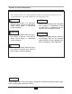
Product & Safety Information Definitions The following terms are used throughout this manual to bring attention to the presence of potential hazards or important information concerning the product. DANGER NOTICE Indicates the presence of a hazardous situation which, if ignored, will result in death, serious injury or substantial property damage. Indicates special instructions on installation, operation or maintenance, which are important to equipment but not related to personal injury hazards.
Product & Safety Information DANGER WARNING Do not use this appliance if any part has been under water. Immediately call a qualified service technician to inspect the appliance and to replace any part of the control system which has been under water. Qualified Installer: Prior to installing this product read all instructions included in this manual and all accompanying manuals/documents with this appliance. Perform all installation steps required in these manuals in the proper order given.
Pre-Installation Items SECTION I - Pre-Installation Items Before locating the PRESTIGE Excellence check for convenient locations to: Code Compliance - - - - Heating system piping - Gas supply piping - This product must be installed in accordance to the following: - - All applicable local, state, national and provincial codes, ordinances, regulations and laws.
Pre-Installation Items Recommended Clearances Residential Garage Installations The PRESTIGE Excellence is approved for zero clearance to combustibles, excluding vent and boiler piping. - - When installing the PRESTIGE Excellence in a residential garage, the following special precautions per NFPA 54/ANSI Z223.1 must be taken: Boiler Piping - 1/4 inch from combustible materials. - Reference the appropriate vent supplement for clearance requirements.
Combustion Air and Venting SECTION II - Combustion Air and Venting Potential contaminating products Combustion Air Contamination - Spray cans containing chloro/fluorocarbons - Chlorinated wax - WARNING If the PRESTIGE Excellence combustion air inlet is located in any area likely to cause or contain contamination, or if products, which would contaminate the air cannot be removed, the combustion air must be repiped and terminated to another location.
Combustion Air and Venting Ventilation and Combustion Air Requirements - Direct Vent Ventilation and Combustion Air Requirements - Category IV A Direct Vent appliance utilizes uncontaminated outdoor air (piped directly to the appliance) for combustion. A Category IV appliance utilizes uncontaminated indoor or outdoor air (surrounding the appliance) for combustion.
Combustion Air and Venting Methods of Accessing Combustion Air Into A Space - Category IV Indoor Combustion Air - NOTICE The methods listed in this section for accessing Indoor Combustion Air assume that the infiltration rate is adequate and not less than .40 ACH. For infiltration rates less than .40 ACH, reference the NFPA 54 National Fuel Gas Code for additional guidance. The minimum dimension of air openings shall be not less than 3 inches. Combining spaces in different stories.
Combustion Air and Venting Fig. 2: - All Combustion Air from Outdoors Through One Permanent Air Opening Fig. 3: All Combustion Air from Outdoors Through Ventilated Attic Not less than the sum of the areas of all vent connectors in the space. Two Permanent Openings Method. Two permanent openings, one commencing within 12 in. of the top and one commencing within 12 in. of the bottom of the enclosure, shall be provided.
Combustion Air and Venting Combination of Indoor and Outdoor Combustion Air The PRESTIGE Excellence is certified per ANSI Z21.13 as a Category IV or Direct Vent (sealed combustion) appliance. A Category IV appliance utilizes uncontaminated indoor or outdoor air (surrounding the appliance) for combustion. A Direct Vent appliance utilizes uncontaminated outdoor air (piped directly to the appliance) for combustion.
Combustion Air and Venting Removal of an Existing Boiler from a Common Vent System 5. Test for spillage at the draft hood relief opening after 5 minutes of main burner operation. Use the flame of a match or candle, or smoke from a cigarette, cigar or pipe. BEST PRACTICE When an existing boiler is removed from a common venting system, the common venting system is likely to be too large for proper venting of the remaining appliances.
Combustion Air and Venting Commonwealth of Massachusetts Installations Only For direct-vent appliances, mechanicalvent heating appliances or domestic hot water equipment, where the bottom of the vent terminal and the air intake is installed below four feet above grade the following requirements must be satisfied: 4. A metal or plastic identification plate shall be mounted at the exterior of the building, four feet directly above the location of vent terminal.
Unit Preparations SECTION III - Unit Preparations Wall Mounting Guidelines Handling Instructions 1. The wall-mounting bracket is designed for stud spacing of 12 inch or 16 inch on centers. For unconventional stud spacing, a solid / secure mounting surface must be provided for installation of the bracket. The PRESTIGE Excellence is generally easier to handle and maneuver once removed from the shipping carton. 2.
Unit Preparations Wall Bracket Installation - Stud Walls 5. Install the anchors (provided) flush or slightly recessed in the drilled holes with threaded side facing down. 1. To distribute the weight of the boiler evenly when mounting onto a stud wall it is recommended to use the PRESTIGE Wall Frame kit. 6. Reposition the bracket on the wall and align mounting slots/holes. Insert the two bolts (provided) through the mounting slots/holes and loosely tighten. 2.
Boiler Piping SECTION IV - Boiler Piping - General Piping Requirements - All plumbing must meet or exceed all local, state and national plumbing codes. - Use isolation valves to isolate system components. - - - Support all piping using hangers. DO NOT support piping by the unit or its components. - Install unions for easy removal of the PRESTIGE Excellence from the system piping. - If plastic pipe is used for boiler piping, it must have a maximum oxygen diffusion rate of 0.
Boiler Piping Pressure Relief Valve (Supplied with Boiler) 3/4" Street Elbow Air Vent Drain Piping Directed to a Suitable Place of Drainage Boiler Return Connection Boiler Supply Connection Fig. 5: Pressure Relief Valve and Boiler Drain Valve Installation Boiler Air Vent Boiler Drain Valve (field supplied) 1. Make sure to fully tighten the cap on the air vent on initial installation.
Boiler Piping Additional Limit Control Boiler System Piping Applications If a separate LWCO device is required by certain local jurisdictions or when the boiler is installed above the system piping, the following guidelines must be followed: - - BEST PRACTICE It is recommended on all piping applications to utilize a primary/secondary piping arrangement as a means to provide freeze protection of the boiler, which is an integral function of the boiler control.
Boiler Piping System Piping - Zone Circulators Connect the expansion tank to an air separator only if the air separator is located on the suction side (inlet) of the system circulator. Always locate and install the system fill connection at the same location as the expansion tank connection to the system. Connect the PRESTIGE Excellence to the system piping as shown in Fig. 9 page 20 when zoning with zone circulators. The installer must provide a separate circulator for each zone of space heating.
Boiler Piping System Piping - Radiant Heating NOTICE The addition of the high temperature limit is important when the PRESTIGE Excellence has completed a DHW call, which requires a high primary supply water temperature. The heat exchanger design of the PRESTIGE allows operation in a condensing mode. This feature requires no regulation of the return temperature back to the boiler in radiant heating applications.
Boiler Piping Fig.
Boiler Piping Note: Reference Fig. 23, page 35 for Prestige Wiring. AUX (Inside cabinet) ZC1 ZC2 Note: ZC1 and ZC2 circulators controlled by SZC5 Zone Panel. Fig. 9: System Piping - Zoning with Zone Circulators Note: Reference Fig. 24, page 35 for Prestige Wiring. D.V. BC1 AUX (Inside cabinet) Z.V. Z.V. SC1 SYS Fig.
Boiler Piping Note: Reference Fig. 25, page 36 for Prestige Wiring. D.V. AUX BC1 (Inside cabinet) prestige Z.V. Z.V. Note: Verify AUX circulator is properly sized to overcome the system pressure drop and provide adequate flow through the boiler system. Fig. 11: System Piping - Multiple Zone Valve with Single System/Boiler Circulator Note: Reference Fig. 26, page 36 for Prestige Wiring.
Installing Vent/Combustion Air & Condensate Drain SECTION V - Installing Vent / Combustion Air & Condensate Drain WARNING Ensure installation of the condensate drain assembly included the metal washer. Failure to comply could result in the trap assembly dislocating from the boiler. Installing Vent and Combustion Air DANGER The PRESTIGE Excellence must be vented and supplied with combustion air as shown in the PRESTIGE Vent Supplement, included in the boiler installation envelope.
Installing Vent/Combustion Air & Condensate Drain 9. The PRESTIGE Solo will typically produce a condensate that is considered slightly acidic with a pH content below 3.0. Install a neutralizing filter if required by authority having jurisdiction. NOTICE The drain line materials must be an approved material by the authority having jurisdiction. In absence of such authority, PVC and CPVC piping must comply with ASTM D1785 or D2845.
Gas Piping SECTION VI - Gas Piping 7. Use pipe dope compatible with natural and propane gases. Apply sparingly only to the male threads of pipe joints so that pipe dope does not block gas flow. Gas Supply Piping Connection NOTICE WARNING The gas supply piping must be installed in accordance to all applicable local, state and national codes and utility requirements. Failure to apply pipe dope as detailed above can result in severe personal injury, death or substantial property damage. 1.
Gas Piping NATURAL GAS 2. Install 100% lockup gas pressure regulator in the gas supply line if inlet pressure can exceed 13”w.c at any time. Adjust the lockup pressure regulator for 13”w.c maximum. Pipe Sizing - Natural Gas Refer to Table 1 for schedule 40 metallic pipe length and diameter requirements for natural gas, based on rated PRESTIGE Excellence input (divide by 1,000 to obtain cubic feet per hour). - - WARNING DO NOT adjust or attempt to measure gas valve outlet pressure.
Gas Piping PROPANE GAS WARNING Pipe Sizing - Propane Gas DO NOT adjust or attempt to measure gas valve outlet pressure. The gas valve is factory-set for the correct outlet pressure. This setting is suitable for natural gas and propane and requires no field adjustment. Attempts by the installer to adjust or measure the gas valve outlet pressure could result in damage to the valve, causing potential severe personal injury, death or substantial property damage.
Gas Piping Throttle Screw LP Orifice (if required) Gas Valve Gasket Offset Pressure Cover Screw Inlet Gas Pressure Port Gas Valve Venturi Fig.
Internal Wiring SECTION VII - Internal Wiring WARNING ELECTRICAL SHOCK HAZARD. For your safety, disconnect electrical power supply to the unit before servicing or making any electrical connections to avoid possible electric shock hazard. Failure to do so can cause severe personal injury or death. Location of Fuses CAUTION Prior to servicing, label all wires before disconnecting. Wiring errors can cause improper and dangerous operation. Verify proper wiring and operation after servicing. Fig.
Internal Wiring Fig.
External Wiring SECTION VIII- External Wiring Circulator & Diverter Valve Wiring Installation Compliance The PRESTIGE Excellence contains a prewired Boiler circulator as well as a Diverter Valve. The Boiler circulator is enabled for any CH1, CH2, or DHW call. The Diverter Valve will direct water flow to the CH Supply Connection at the bottom of the boiler during a CH1 or CH2 call or to the internal Indirect Water Heater during a DHW call.
External Wiring Alarm Wiring WARNING The alarm contact closes whenever the Prestige is in a soft or hard lockout. This dry contact can be connected to an external monitoring system or other indicator to alert the operator that the Prestige is locked out. Simultaneous CH1 and CH2 calls will result in the PRESTIGE operating at the highest target temperature.
External Wiring Outdoor Sensor Wiring External Modulation Control The PRESTIGE firing rate can be controlled by an external modulating boiler controller. See page 62 for external modulation signal wiring and setup. The Outdoor Reset function and Warm Weather Shutdown (WWSD) features require the connection of the included outdoor temperature sensor. See page 61 for outdoor sensor installation and setup.
AUX Diverter Valve CH (1) Pump External Wiring Fig.
AUX Diverter Valve CH (1) Pump External Wiring Fig.
External Wiring Note: Reference Fig. 9, page 20 for System Piping. CH (1) Pump Diverter Valve AUX ZC1 Fig. 23: Prestige Wiring - Zoning with Zone Circulators ZC2 Note: Reference Fig. 10, page 20 for System Piping. CH (1) Pump Diverter Valve SYS Fig.
External Wiring Note: Reference Fig. 11, page 21 for System Piping. CH (1) Pump Diverter Valve AUX Fig. 25: Prestige Wiring - Multiple Zone Valve with Single System/Boiler Circulator Note: Reference Fig. 12, page 21 for System Piping. CH (1) Pump Diverter Valve AUX Fig.
Trimax Operation SECTION IX- Trimax Operation The Trimax Boiler Management System is designed to be flexible yet easy to use. Trimax monitors and controls the Prestige to provide heat as efficiently as possible. Trimax includes many advanced features which previously were not available in the Prestige. • Two central/space heating (CH) call inputs with separate outdoor reset curves. • Domestic Hot Water (DHW) call input with optional priority.
Trimax Operation Trimax Navigation Navigation is performed through four arrow buttons UP, DOWN, LEFT, RIGHT with a center OK button for making selections and entering information. The INSTALLER button (the small round button) provides the installing contractor with full access to all available features after entering a password. Reference the Trimax Control Supplement for Installer level functions.
Trimax Operation Trimax Menu Structure Home Screen Main Menu EZ Setup Menu CH/DHW Operation Menu Heating Enabled Boiler Information Menu Boiler Information b bbb f bbb b bb f ed cebd cba de f b b ed cba a abcc de f ab d e abc b bbb f ed bbb b bb f ed cb cba de f a abc de f bb d cba gb c b f a d abc 39
Trimax Operation Home Screen The Home Screen presents status information in a very user friendly way so that the current state of the boiler can be quickly accessed. The Prestige is represented in the center of the Home Screen. Basic operating information such as supply and return temperatures are displayed as well as current burner status. A flame symbol is displayed when the unit is fired. The flame size changes to indicate the current firing rate.
Trimax Operation Status Line Message Standby CH Demand DHW Demand DHW Priority Priority Timeout External Demand Slave Operation Manual Operation CH Burner Delay DHW Burner Delay CH Setpoint Reached DHW Setpoint Reached CH Post Pump DHW Post Pump Freeze Protection Boiler Protection Lockout Description Status Line Messages Description Indicates that the Prestige is ready to respond when a demand is received. A central heating call has been received. A domestic hot water call has been received.
Trimax Operation Main Menu The Main Menu can be entered from the Home Screen by pressing the OK button. The menu system utilizes icons to represent each selection. The currently selected menu is displayed as a reversed image with a text description shown at the top of the display. Menus can be entered by highlighting the desired icon and pressing the OK button. Press OK Button Currently selected menu The CH / DHW Operation Menu can be accessed by selecting this icon.
Trimax Operation EZ Setup Navigation: Home Screen>Main Menu>EZ Setup The EZ Setup menus provide a simple way to quickly customize the Trimax for each installation. EZ Setup prompts the user to make selections which allows the Prestige to be setup very quickly without searching through long lists of settings and manually making adjustments.
Trimax Operation Select CH1 Reset Curve Default: Finned Tube Baseboard Select CH1 Reset Curve prompts the installer to select an outdoor reset curve for a CH1 heating call when an Outdoor Reset option is chosen in Select CH Demand. Outdoor reset curve presets are available to cover most applications. The outdoor reset curve can also be adjusted to any desired settings in the Installer Menu.
Trimax Operation Domestic Hot Water EZ Setup Navigation: Home Screen>Main Menu>EZ Setup>DHW EZ Setup Domestic Hot Water EZ Setup allows the installer to quickly customize the domestic hot water settings for the application. Select DHW Demand Default: Sensor Select DHW Demand prompts the installer to select the type of device which will generate a DHW call. Press the UP or DOWN buttons to select the DHW Demand type then press the OK button to store the setting.
Trimax Operation EZ Setup Reset EZ Setup Reset Navigation: Home Screen>Main Menu>EZ Setup>EZ Setup Reset EZ Setup Reset allows the installer to reset all EZ Setup settings back to the original factory defaults. Follow the on screen instructions to reset all EZ Setup settings back to the original factory defaults. Press OK button to restore factory settings. Any other button to keep current settings. NOTICE The EZ Setup Reset function will set Select DHW Demand to Switch.
Trimax Operation CH/DHW Operation Navigation: Home Screen>Main Menu>CH / DHW Operation CH / DHW Operation provides a simple way to disable either the central heating or domestic hot water functions of the Prestige. Operation can be enabled and disabled by selecting the central heating or domestic hot water icon then pressing the OK button to toggle between enabled and disabled. An icon with an X through it indicates that function has been disabled.
Trimax Operation Information Item Boiler Status Heating Call DHW Call Boiler Firing Rate Flame Ionization Current Boiler Setpoint Information Items Description Displays the current operating state of the Prestige. This is the same as the status line on the home screen. Displays if a central heating call is present. Displays if a domestic hot water call is present Displays the current firing rate of the Prestige. Displays the current flame ionization current from the ignitor.
Trimax Operation Lockout History b bbb f bbb b bb f ed cebd cba de f b b ed cba a abcc de f ab d e abc b bbb f ed bbb b bb f ed cb cba de f a abc de f bb d cba gb c b f a d abc Navigation: Home Screen>Main Menu>Boiler Information>Lockout History Lockout History records the last eight lockouts. Each line contains a lockout description followed by how long ago the lockout occurred. Six lockouts are displayed on the screen at one time. Press the UP or DOWN buttons to scroll through additional lockouts.
Trimax Operation Lockout Screen The Lockout Screen replaces the Home Screen if a lockout occurs. The screen backlight will also illuminate constantly while the Prestige is locked out. Pressing any arrow button will return to the Home Screen so that additional troubleshooting can be performed. See pages 51 and 52 for a list of lockouts and descriptions. The lockout message is displayed at the top of the screen Low Water The first sentence gives a description of the lockout.
Trimax Operation Code Lockout Message E2 False Flame E1 Manual Reset Hard Lockouts Failed Ignition Description The burner failed to light after 5 ignition attempts. A flame is being detected prior to ignition. E3 High Boiler Temperature E5 Blower Speed E8 Flame Circuit Error E9 Gas Valve Circuit Error E13 Reset Limit Reached E15 Sensor Drift E16 Supply Sensor Stuck Supply sensor reading is not changing. E17 Return Sensor Stuck Return sensor reading is not changing.
Trimax Operation Code Lockout Message Automatic Reset Soft Lockouts Description E7 High Flue Temperature Flue temperature exceeds high limit. E25 Internal Control Fault CRC check error.
Start-Up Preparation SECTION X - Start-Up Preparation Chlorinated Water Do not use the PRESTIGE Excellence to heat a swimming pool or spa directly. NOTICE Requirements below must be met for warranty coverage of Prestige heat exchangers. A thorough cleaning of any existing system, using approved heating system cleaning agents is required prior to installation of the Prestige boiler. System should be treated with an approved inhibitor after filling for long term protection.
Start-Up Preparation • Verify pH and inhibitor level per inhibitor manufacturer’s specs; add inhibitor if necessary. NOTICE System fluid, including additives, must be practically non-toxic, having a toxicity rating or Class of 1, as listed in Clinical Toxicology of Commercial Products.
Start-Up Preparation - WARNING Unrepaired system leaks will cause continual makeup water to be added to the boiler. Continual makeup water will cause mineral buildup within the heat exchanger, reducing the heat transfer, causing possible heat buildup and eventual heat exchanger failure. - - - Check Low Water Cut-Off Device - - The PRESTIGE Excellence is provided with a factory installed LWCO device that measures system pressure of more than 10 psi.
Start-Up Procedures SECTION XI - Start-Up Procedures PRESTIGE Excellence Start-Up Final Checks Before Start-Up c c c c c c 1. Press the ON-OFF button located on the front control panel to the OFF position. Turn ON the electrical supply/service to the unit. Read page 37 through 52 regarding the operation of the Trimax Boiler Management System. 2. Read and follow the Operating Instructions outlined on page 60.
Start-Up Procedures c Check Vent Piping and Combustion Air Piping. 2. Test for CO2 or O2 and for CO during high firing rate. The combustion readings should be within the range listed in Table 4. The CO level should not exceed 100 ppm when combustion is correct. Perform the following procedure to manually place the burner into high fire. Check for gas-tight seal at every connection and seam of the venting and combustion air piping.
Start-Up Procedures e. Press the LEFT and RIGHT buttons to adjust the firing rate from 1% to 100%. Hold down the LEFT or RIGHT button to rapidly increase or decrease the firing rate. Clockwise adjustment of the throttle screw at High Fire: O2 increases and CO2 decreases Table 4: Recommended Combustion Levels Natural Gas Propane O2 Min. 2.30% 2.70% CO2 Min. 8.80% 10.70% 100 ppm 100 ppm O2 Max. CO2 Max. CO Max. 5.30% 10.50% 3.
Start-Up Procedures c Test High Temperature Limit 9. Press any ARROW button to return to the Home Screen. The high temperature limit can be temporarily lowered from 210ºF [99ºC] to 102ºF [39ºC] for testing. 10. Press the round INSTALLER button. 11. Press the OK button while the CH & DHW Settings icon is highlighted. 1. Press the round INSTALLER button. Reference Fig. 31, page 38. 12. Press the DOWN button to highlight the Boiler Settings icon then press the OK button. 2.
Start-Up Procedures WARNING FOR YOUR SAFETY READ BEFORE LIGHTING If you do not follow these instructions exactly, a fire or explosion may result causing property damage, personal injury or loss of life. A. This appliance does not have a pilot. It is • If you cannot reach your gas supplier, call the fire department. equipped with an ignition device which automatically lights the burner. DO NOT try to light the burner by hand. C. Use only your hand to turn the external manual gas valve. Never use tools.
Outdoor Reset Control SECTION XII - Outdoor Reset Control 4. Avoid mounting the outdoor sensor in areas subjected to excessive moisture. The use of the outdoor reset function is required to optimize boiler efficiency, see notice below. If the outdoor sensor is not installed before turning on the boiler, an Outdoor Sensor Open error (E96) will be displayed. The error will not prevent the boiler from operating.
External Modulating Control SECTION XIII - External Modulating Control Trimax Adjustment Wiring the Modulating Controller 1. Use the Heating EZ Setup function to set the CH Demand to 0-10V Modulation Signal. Reference page 43 for the Heating EZ Setup function. The Trimax control must be programmed to accept the 0-10 VDC signal from the external modulating boiler control.
External Modulating Control Factory Trimax Setting HEATING SETTING FACTORY DEFAULT Demand Switch & Outdoor Reset CH1 Maximum Setpoint 180°F [82°C] Heating Operation Absolute Max CH Setpoint CH1 Minimum Setpoint Reset Curve Coldest Day Enabled 140°F 60°C] Warm Weather Shutdown OFF Disabled Frost Protection Setpoint -22°F [-30°C] CH Call Blocking 1 minute System Pump Enabled 0°F [0°C] CH1/CH2 DOMESTIC SETTING DHW Operation FACTORY DEFAULT Enabled Boiler DHW Setpoint 186°F [86°C] DH
Check-Out Procedures SECTION XIV- Check-Out Procedures c NOTICE Perform the following check-out procedures as outlined and check off items as completed. When procedures are completed, the installer should complete the installation record on page 65. c c Check-Out Procedures c c c c c c c c c c c c Boiler system fluid chemistry checked and verified as outlined on page 53. c Boiler system was completely flushed to remove any debris/sediment.
Installation Record SECTION XV - Installation Record PRESTIGE Model Number: Serial Number: Date of Installation: Fuel: Natural Gas Propane Measured Rate of Input: Btu/hr Combustion Readings: CO2 % O2 % CO ppm The following items were completed during installation: Installation instructions have been followed and completed Check-out procedures have been followed and completed Information regarding the unit and installation received and left with owner / maintenance personnel.
Maintenance Schedules SECTION XVI - Maintenance Schedule Owner Maintenance At least on an annual basis the following maintenance should be performed by a qualified service technician: - Check the area around the unit. - Check the temperature and pressure gauges. Service Technician Periodically: - General - - - - - - - - - - - Attend to any reported problems. Inspect the interior of the boiler jacket area; clean and vacuum if necessary.
Maintenance Procedures SECTION XVII- Maintenance Procedures Verify that combustion air inlet area is free of any contaminates. Refer to the materials listed on page 5 of this manual. If any of these products are in the area from which the unit takes its combustion air, they must be removed immediately or the combustion air intake must be relocated to another area.
Maintenance Procedures Clean Condensate Drain Assembly Inspect Vent and Combustion Air Piping 2. Empty any water from the trap and drain assembly. Flush with fresh water as necessary to clean. Verify that the combustion air inlet piping is connected, sealed and properly supported. 1. Loosen the retaining nut from the condensate drain assembly and disconnect the assembly from the boiler. Visually inspect the venting system and combustion air piping for blockage, deterioration of gaskets or leakage.
Maintenance Procedures Check Expansion Tank WARNING Before manually operating the pressure relief valve, ensure the discharge piping is directed to a suitable place of disposal to avoid a potential scald hazard. The discharge piping must be full size without restriction and installed to permit complete drainage of both the valve and line. Refer to Section IV - Boiler Piping for recommended location of the expansion tank and air eliminators.
Maintenance Procedures Check Control Wiring Carefully remove the burner mounting plate assembly from the heat exchanger. Ensure combustion chamber insulation is not damaged during removal of burner mounting plate assembly. See WARNING on page 72. Inspect all control wiring. Ensure wiring is in good condition and properly connected. Check Control Settings Remove the burner head mounting screws and remove the burner head. Inspect the burner head for deterioration.
Maintenance Procedures Check Flame Signal 4. Disconnect the wiring harness connectors from the blower and remove the blower retaining screws or nuts. Remove the blower from the unit. The flame signal can be read from the Boiler Information screen. It should be a min. 1μ Α −DC. 5. Remove the mounting nuts securing the burner mounting plate to the heat exchanger and set aside. Check the ignitor for fouling or damaged insulation if a low flame signal is read. 6.
Maintenance Procedures Review With Owner 15. Once the boiler has been completely flushed, return the boiler and system piping back to operation. Ensure the owner understands the importance to perform the maintenance schedule specified in this manual. 16. Perform the required startup and checkout procedures as outlined on pages 53 to 64. Remind the owner of the importance to call a licensed contractor should the unit or system exhibit any unusual behavior.
Replacement Parts Use only genuine ACV-Triangle Tube replacement parts to ensure warranty coverage and to avoid damage to appliance and improper operation of appliance. Contact ACV-Triangle Tube at 856-228-8881 or www.triangletube.com for list of distributors nearest you. WARNING Replacement parts must be purchased through a local ACV-Triangle Tube distributor. When ordering part please provide the model number and description and/or part number of replacement part. 6 7 5 8 1 4 4 2 3 Fig.
Replacement Parts 2 12 4 3 10 14 1 5 13 15 16 9 6 11 4 8 7 Fig.
Replacement Parts 8 7 3 6 9 4 2 5 1 Fig.
Replacement Parts 5 6 8 7 2 1 4 3 Fig. 36: PRESTIGE Excellence Control Enclosure Item 1 Part # PTRKIT109 3 PTSWI02 2 PTSWI01 4 PTRKIT108 6 PTRKIT207 5 7 8 PTRKIT205 PTCON19 PTGRO01 9 PTFUSE02 11 PTFUSE03 10 PTFUSE01 Description Pressure Gauge and Fitting Power Switch Power Switch Cover Control Enclosure TriMax Control Module TriMax Display Module Control Enclosure Cover Igniter Cable Grommet TriMax Control Module 5A Fuse (Not Shown) Circulator 2.
Product Specifications 24 3/4” [628 mm] 21 1/4” [540 mm] 14 3/4” [377 mm] 3” Combustion Air Inlet 3/4” NPSC Pressure Relief Valve 37 1/2” [953 mm] 12 1/4” [310 mm] 3” Vent Outlet 7 1/2” [190 mm] 11 3/4” [300 mm] 16” [405 mm] 19” [479 mm] Front View PRESTIGE Excellence 110 77 1/2 ” NPSC Boiler Drain 1” NPT Boiler Return 1/2” NPT Gas Connection 1” NPT Boiler Supply
Product Specifications 21 1/4” [540 mm] 15 1/4” [390 mm] 11 3/4” [300 mm] 3/4” NPSC Pressure Relief Valve 3” Vent Outlet 3” Combustion AIr Inlet 2 3/4” 1/2” NPT Gas Connection [70mm] 7 3/4” [200 mm] 16 3/8” [416 mm] Side View PRESTIGE Excellence 110 78 1/2” NPSC Boiler Drain 1” NPT Boiler Supply 1” NPT Boiler Return
Product Specifications 11.1/4" [286 mm] 3/4” NPT DHW Outlet 3/4” NPT DHW Inlet 4 3/8" [110 mm] 3 1/2" [87 mm] 3/4” NPSC Aux.
Product Specifications Boiler Model Fuel DOE Heating Capacity Note 1 & 4 Input Note 4 Net AHRI Rating Note 2 Excellence Natural 99,000 110,000 86,000 95% 190/86 Excellence Propane 87,000 97,000 76,000 95% 190/86 Note 1: Note 2: The heating capacity of the PRESTIGE Excellence is based on the test requirements of the U.S. Department of Energy. Note 3: Note 4: The AHRI rating is based on a piping and pick up allowance of 1.15.
Product Specifications Graph 2: Pressure Drop Comparison Excellence vs Grundfos UPS 15-58F Note: Minimum allowable flow rate at full input: 5 gpm 81
prestige Excellence Indirect Water Heater Part 2 of 2 LI STED * I N S TALLAT I O N AN D MAI N T E NAN C E * M A N U A L WARNING IMPORTANT • • • • • • Revised 1/7/14 Before proceeding with installation and operation, read entire manual carefully. Failure to do so can cause injury or property damage. When receiving the PRESTIGE Excellence, any claims for damage or shortage in shipment must be filed immediately against the transportation company by the consignee.
Tables of Contents Product & Safety Information . . . . . . . . . . . . . . . . . . . . . . . . . . . . . . . . . . 1-2 Pre-Installation . . . . . . . . . . . . . . . . . . . . . . . . . . . . . . . . . . . . . . . . . . . . . . 3-4 Installation - Domestic Piping Temperature & Pressure (T&P) Relief Valve . . . . . . . . . . . . . . . . . .5 Drain Valve . . . . . . . . . . . . . . . . . . . . . . . . . . . . . . . . . . . . . . . . . . . .6 Automatic Air Vent . . . . . . . . . . . . . . . . . . . . . . . .
Product & Safety Information Definitions The following terms are used throughout this manual to bring attention to the presence of potential hazards or important information concerning the product. DANGER NOTICE Indicates the presence of a hazardous situation which, if ignored, will result in death, serious injury or substantial property damage. Indicates special instructions on installation, operation or maintenance, which are important to equipment but not related to personal injury hazards.
Product & Safety Information CAUTION WARNING Protection must be taken against excessive temperature and pressure! Bacteria can develop in the domestic water system if certain minimum water temperatures are not maintained. TO PROTECT AGAINST EXCESSIVE TEMPERATURE AND PRESSURE DANGER • HOT WATER CAN SCALD! Water temperature over 125ºF can cause severe burns instantly or death from scalds. • • • Children, disabled and elderly are at highest risk of being scalded.
Pre-Installation Codes Compliance 2. The pressure of the heat transfer medium is maintained less than the normal minimum operating pressure of the potable water system Installation of the Excellence Water Heater must conform with the instructions in this manual and where applicable: • • Exception: Steam complying with section #1 above. local, state, provincial, and national codes, laws, regulations and ordinances. 3.
Pre-Installation BEST PRACTICE BEST PRACTICE In hard water areas (more than 7 grains of hardness) soften the cold domestic supply water to the appliance to prevent scaling. To provide serviceability to the unit it is recommended that the following clearances be maintained: Top boiler jacket - 24 inches. Front - 24 inches. NOTICE Bottom boiler piping - 24 inches. Any water conditioning system must be installed and maintained in accordance with manufacturer’s specifications.
Installation - Domestic Piping Temperature & Pressure (T&P) Relief Valve • CAUTION To reduce risk of excessive pressures and temperatures in the water heater, install temperature and pressure protective equipment required by local codes, but no less than a combination temperature and pressure relief valve certified by a nationally recognized testing laboratory that maintains periodic inspection of production of listed equipment or materials, as meeting the requirements for Relief Valves and Automatic Ga
Installation - Domestic Piping Drain Valve Thermal Expansion If a backflow preventer, check valve or pressure reducing valve is piped on cold water supply piping of water heater, install an expansion tank on cold water supply line to prevent normal thermal expansion from repeatedly forcing open T&P relief valve. Drain valve and fittings are supplied by others. Standard Installation • • Install a tee connection at the domestic cold water inlet, as shown in Fig. 4, pages 9.
Installation - Domestic Piping • • All plumbing must meet or exceed all local, state and national plumbing codes. by an aquastat. The maximum recommended setting of the aquastat is 10ºF lower than the thermostatic mixing valve setting. Use pipe dope or tape suitable for potable water systems. DANGER • Use isolation valves to isolate system components.
Installation - Domestic Piping DHW Hot Water Outlet T&P Valve (Drain Piping Not Shown) DHW Aux. Connection DHW Cold Water Inlet Air Vent Connection Fig. 2: Standard Installation of the T&P Relief Valve T&P Valve (Drain Piping Not Shown) Drain Dip Tube 3/4” Brass Tee 3/4” Brass Close Nipple DHW Hot Water Outlet DHW Aux. Connection Air Vent Connection Fig.
Installation - Piping Diagrams Fig. 4: Standard Installation Domestic Piping Excellence Series Fig. 5: Standard Installation Domestic Piping with Optional Recirculation Excellence Series 1. 2. 3. 4. 5. Shut-off valve Flow check valve Mixing valve with check valve Vacuum Breaker * Unions 6. 7. 8 9. 9 Backflow preventer or pressure reducing valve(*) Circulator (controlled by aquastat) Domestic drain valve Thermal expansion tank (potable) (*) Optional devices may be required by local codes.
Installation - Piping Diagrams Fig. 6: Domestic Piping with Optional Storage Tank 1. 2. 3. 4. 6. 7. 8 9. Mixing valve with check valve Flow check valve Shut-off valve Backflow preventer or pressure reducing valve(*) Thermal expansion tank Circulator (controlled by aquastat) Domestic drain valve Vacuum Breaker * (*) Optional devices may be required by local codes.
Water Heater Start-Up Filling the Inner (Domestic Water) Tank • • WARNING Do not use automotive, ethylene glycol or petroleum-based antifreeze. Do not use any undiluted antifreeze. This can cause severe personal injury, death or substantial property damage. CAUTION Never use the Excellence unless inner and outer tank of the water heater is completely filled with water. Inner tank of the Excellence water heater must be completely filled and pressurized before pressurizing outer tank.
Water Heater Start-Up DANGER HOT WATER CAN SCALD! • Water temperatures over 125ºF can cause severe burns instantly, or death from scalds. • Consumer Product Safety Commission and some states recommend temperatures settings of 130ºF or less. Setting thermostat higher than 130ºF will increase risk of scald injury and cause severe personal injury or death. • • • Feel water before bathing or showering.
Water Heater Start-Up Domestic Hot Water EZ Setup Navigation: Home Screen>Main Menu>EZ Setup>DHW EZ Setup Domestic Hot Water EZ Setup allows the installer to quickly customize the domestic hot water settings for the application. Select DHW Demand Default: Sensor Select DHW Demand prompts the installer to select the type of device which will generate a DHW call. Press the UP or DOWN buttons to select the DHW Demand type then press the OK button to store the setting.
Additional DHW Feature DHW Frost Protection The Indirect Water Heater (IDWH) Sensor used in the Prestige Excellence provides a Frost Protection feature to the water heater. The Frost Protection feature is designed to protect the Excellence water heater from a potential freeze up. Frost Protection will generate a DHW call once the IDWH temperature falls below 42º F [6ºC].
Additional DHW Feature Factory Trimax Setting HEATING SETTING FACTORY DEFAULT Demand Switch & Outdoor Reset CH1 Maximum Setpoint 180°F [82°C] Heating Operation Absolute Max CH Setpoint CH1 Minimum Setpoint Reset Curve Coldest Day Enabled 140°F 60°C] Warm Weather Shutdown OFF Disabled Frost Protection Setpoint -22°F [-30°C] CH Call Blocking 1 minute System Pump Enabled 0°F [0°C] CH1/CH2 DOMESTIC SETTING DHW Operation FACTORY DEFAULT Enabled Boiler DHW Setpoint 186°F [86°C] DHW On
Water Heater Maintenance Maintenance Schedule Check function of field-installed controls and valves. See component manufacturer’s instructions. Annual service by qualified service technician should include the following: Review homeowner’s maintenance responsibilities and their frequencies, including any not listed in the following section. Any procedure required by local codes. Check air vent operation. Verify system pressure.
Water Heater Maintenance If antifreeze is used in boiler water, check concentration. Boiler water (including additives) must be practically non-toxic, having toxicity rating or class of 1, as listed in Clinical Toxicology of Commercial Products. A maximum 50/50 mixture of inhibited propylene glycol is recommended. Follow antifreeze manufacturer’s instruction. WARNING Draining Inner (Domestic Water) Tank (See Domestic Piping Fig. 4 page 9) 1. Disconnect power supply to water heater.
Replacement Parts WARNING Replacement parts must be purchased through a local ACV-Triangle Tube distributor. When ordering part please provide the model number and description and/or part number of replacement part. Use only gen- uine ACV-Triangle Tube replacement parts to ensure warranty coverage and to avoid damage to appliance and improper operation of appliance. Contact ACV-Triangle Tube at 856-228-8881 or www.triangletube.com for list of distributors nearest you. 3 2 1 Fig.
Water Heater Specifications 24 3/4” [628 mm] 21 1/4” [540 mm] 14 3/4” [377 mm] 3” Combustion Air Inlet 3/4” NPSC Pressure Relief Valve 37 1/2” [953 mm] 12 1/4” [310 mm] 3” Vent Outlet 7 1/2” [190 mm] 11 3/4” [300 mm] 16” [405 mm] Front View PRESTIGE Excellence 110 19” [479 mm] 19 1/2 ” NPSC Boiler Drain 1” NPT Boiler Return 1/2” NPT Gas Connection 1” NPT Boiler Supply
Water Heater Specifications 21 1/4” [540 mm] 15 1/4” [390 mm] 11 3/4” [300 mm] 3/4” NPSC Pressure Relief Valve 3” Vent Outlet 3” Combustion AIr Inlet 2 3/4” 1/2” NPT Gas Connection [70mm] 7 3/4” [200 mm] 16 3/8” [416 mm] Side View PRESTIGE Excellence 110 20 1/2” NPSC Boiler Drain 1” NPT Boiler Supply 1” NPT Boiler Return
Water Heater Specifications 11.1/4" [286 mm] 3/4” NPT DHW Outlet 3/4” NPT DHW Inlet 4 3/8" [110 mm] 3 1/2" [87 mm] 3/4” NPSC Aux.
Water Heater Specifications Performance 22
Notes:
Additional quality water heating equipment available from: ACV-Triangle Tube Smart Indirect Fired Water Heaters - Exclusive Tank-in-Tank design Stainless steel construction Available in 7 sizes Limited LIFETIME residential warranty 6 year limited commercial warranty Self cleaning/self descaling design - For domestic water, snow melting, radiant floor, refrigeration Plates made of stainless steel, with a 99.