MiniSmart Instantaneous Water Heater Prestige Series 3 Boiler Supplement Product Information - Application Installation Maintenance Guide WARNING Before proceeding with installation and operation, read entire manual carefully. Perform all installation steps required in this manual in the proper order given. Failure to adhere to the guidelines within this manual can result in severe personal injury, death or substantial property damage.
Table of Contents PRODUCT AND SAFETY INFORMATION Definitions . . . . . . . . . . . . . . . . . . . . . . . . . . . . . . . . . . . . . . . . . . . . . . . . . . . . . . . . 1 Product Safety Notices . . . . . . . . . . . . . . . . . . . . . . . . . . . . . . . . . . . . . . . . . . . . . . 2 PRE-INSTALLATION ITEMS Code Compliance . . . . . . . . . . . . . . . . . . . . . . . . . . . . . . . . . . . . . . . . . . . . . . . . . . 3 Code Restrictions . . . . . . . . . . . . . . . . . . . . . . . . . . . . . . .
Table of Contents OPTIONAL AQUASTAT INSTALLATION Optional Aquastat Installation -Various Boilers . . . . . . . . . . . . . . . . . . . . . . . . . . . . 18 Optional Aquastat Wiring - Various Boilers. . . . . . . . . . . . . . . . . . . . . . . . . . . . . . . 18 PRODUCT SPECIFICATIONS Product Specifications . . . . . . . . . . . . . . . . . . . . . . . . . . . . . . . . . . . . . . . . . . . . . .
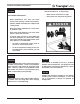
Product and Safety Information DEFINITIONS The following terms are used throughout this manual to bring attention to the presence of potential hazards or to important information concerning the product. NOTICE Indicates special instructions on installation, operation or maintenance, which are important to the equipment but not related to personal injury hazards. DANGER Indicates the presence of a hazardous situation which, if ignored, will result in death, serious injury or substantial property damage.
Product and Safety Information • DANGER HOT WATER CAN SCALD! • Water temperatures over 125°F can cause severe burns instantly or death from scalding • Children, disable and elderly are at highest risk of being scald • Never leave them unattended in or near shower, bathtub or sink. • Never allow small children to use a hot water faucet or draw their own bath.
Pre-Installation Items CODE COMPLIANCE LOCATION / MOUNTING CONSIDERATIONS This product must be installed in accordance with the instructions in this manual and where applicable: This water heater is not intended for outdoor installations - Maintain minimal piping distance between the boiler and the water heater to: With all local, state, provincial and national codes, laws, regulations and ordinances Where recommendations in this manual differ from local or national codes, the local or national codes
General Installation GENERAL INSTALLATION REQUIREMENTS MOUNTING INSTALLATION – STUD WALLS - Ensure all plumbing / piping meets or exceeds all local, state or national codes. 1. Locate a wall stud in the general location of the water heater placement. - Use isolation valves to isolate system components. 2. Place the water heater mounting bracket against the wall centering it along the wall stud. - Install unions for easy removal of the water heater.
General Installation MOUNTING INSTALLATION – SOLID WALLS 5. Mount the bracket onto the water heater using the provided mounting bolts. Ensure the mounting bolts are fully tightened and the bracket is securely fastened to the water heater. See Fig. 2. 1. Locate the general location of the water heater placement. 6. Reposition the bracket and water heater onto the wall and align the bracket and wall anchor holes. Insert the two mounting bolts through the mounting holes and loosely tighten. 2.
Domestic Piping Installation GENERAL REQUIREMENTS - All plumbing must meet or exceed local, state or national plumbing codes. - Support all piping using hangers. DO NOT support piping by the unit or by system components - Install unions for easy removal of the Mini SMART from the system piping - Use isolation valves to isolate the Mini SMART and system components.
Domestic Piping Installation Mix 1 4 5 Hot 2 1 Cold 6 3 Cold Fig. 3 : Mini Smart Domestic Piping 1. Isolation valve 2. Backflow preventer or pressure reducing valve (May be required by code) 3. Thermal expansion tank (optional) 4 Pressure relief valve - 150 psi 5. Mixing valve 6.
Boiler Piping Installation GENERAL REQUIREMENTS - All plumbing must meet or exceed local, state or national plumbing codes. - Support all piping using hangers. DO NOT support piping by the unit or by system components - Install unions for easy removal of the Mini SMART from the system piping - Use isolation valves to isolate the Mini SMART and system components. - If plastic pipe is used for boiler water piping, it must have a maximum oxygen diffusion rate of 0.1 mg/liter-day. - - Reference Fig.
IDWH Sensor Installation & Wiring IDWH SENSOR INSTALLATION 2. Remove the front jacket panel of the PRESTIGE by removing the thumb screw along the upper edge of the jacket panel. Once the thumb screw is removed, pull the panel slightly forward and lift up. Install the IDWH Sensor (provided with water heater) into the bottom coupling of the water heater as shown in Fig.5. 3. Route the wiring from the Sensor to the PRESTIGE boiler.
Program Access of the MCBA Control The display should read C_XX (XX should be a random number from 00 to 99) PROGRAM ACCESS OF THE MCBA CONTROL 5. Press the + or - button to change the display num- NOTICE ber C_XX to read C_54. Press and release the + or - to change the display one number at a time. Press and hold the + or - to rapidly change the display number. The factory default setting for the PRESTIGE Control Module to operate the IDWH is through an aquastat control.
Program Access of the MCBA Control Once a particular parameter is reached, release the STEP button. Wait a second and the display will show the current setting for that parameter in the right two display digits. NOTICE Once a parameter setting value has been revised and stored, if the STEP button is pressed for the next parameter setting the value setting of that parameter will appear. The display will not show P_xx of the next sequential parameter.
IDWH Sensor Parameters IDWH SENSOR PARAMETER DANGER 1. Once the access code number has been stored and accepted in the control module, change the display readout to “Parameter” mode by pressing MODE HOT WATER CAN SCALD! until the display shows • Water temperatures over 125°F can cause severe burns instantly or death from scalding • Children, disable and elderly are at highest risk of being scald • Never leave them unattended in or near shower, bathtub or sink.
IDWH Sensor Parameters WARNING NOTICE The performance specifications listed are based on a DHW storage temperature setting of 140ºF. Setting other then the factory setting of 140ºF will effect the actual performance of the water heater. Parameter 46 has several other possible settings available. The factory setting of the IWH is aquastat control or _13. The required revised setting of the IWH sensor control or _12.
IDWH Sensor Parameters 4. Press the + or - button until the desired “DHW Set Value” setting is achieved. Press STORE to save the setting. The display will flash when the revised setting is accepted. To revise the parameter setting within the PRESTIGE Control Module for DHW “Detention ON” control, the installer must activate the access code for the control module as previously described in the Program Access of the MCBA section on page 10. 5.
IDWH Sensor Parameters DANGER The Frost Protection feature is designed to protect the UNIT from a potential freeze up. The protection is activated once the IDWH Sensor records a domestic temperature of 38ºF. At that time the PRESTIGE boiler will begin the burner function at low input and the DHW circulator will begin circulating. The burner will continue operating at minimum input with the DHW circulator energized until the IDWH Sensor senses a domestic water temperature of 50ºF.
Prestige Parameter Information PRESTIGE FACTORY SETTINGS FOR PARAMETERS 16
Prestige Parameter Information Accessing Boiler Information Information mode NOTICE I NFO The ignition counters and burner hours are split into three two digit numbers. For example: To switch from STANDBY mode to INFORMATION mode, press MODE twice. Key: MODE MODE J 12 .34 .56 Display P ARA I NFO Pressing MODE once Pressing MODE twice Write the numbers down from left to right to arrive at 123,456 CH ignitions. Press STEP until the system displays the information you need.
Optional Aquastat Installation OPTIONAL AQUASTAT INSTALLATION VARIOUS BOILERS OPTIONAL AQUASTAT WIRING - VARIOUS BOILERS. In lieu of the factory supplied sensor the installer may opt to use an aquastat, for this type of application the following parts must be supplied by the installer: - Honeywell L4008A1130 or equivalent - 1/2” NPT X 3” Long Drywell Honeywell 12137A or equivalent WARNING ELECTRICAL SHOCk HAZARD.
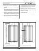
Product Specifications Boiler Supply 3/4” NPSC Boiler Return 1/2” NPSC IDWH Sensor Connection 18” 3” 7 1/2” 1/4” 2” Domestic Wall Surface 1/4” Bottom View Wall Surface Boiler Return 6 1/4” 3/4” NPSC Boiler Supply 4 1/4” 9 1/4” OD 10” Front View 1/2” NPT Domestic hot 1/2” NPT Domestic Cold 1 1/2” Typ Top View NOTE: 1. Domestic capacity is based on an intermittent draw with 50ºF inlet temperature and 120ºF outlet temperature.
Additional quality water heating equipment available from Triangle Tube PRESTIGE CONDENSING WALL MOUNTED BOILERS - 95% AFUE Efficiency (Low temperature application) - Fully modulating - Natural gas or propane - Stainless Steel Construction - Direct vent with standard schedule 40 PVC - Outdoor Reset - Low Nox SMART INDIRECT FIRED WATER HEATERS - Exclusive tank-in-tank design - Stainless steel construction - Available in 8 sizes and 2 models - Limited LIFETIME residential warranty -