Indirect Fired Water Heaters SMART Series TR Series US & Canada Technical Specifications Installation and Maintenance Guide WARNING IMPORTANT • Before proceeding with installation and operation, read entire manual carefully. Failure to do so can cause injury or property damage. • When receiving Phase III® equipment, any claims for damage or shortage in shipment must be filed immediately against the transportation company by the consignee.
Phase III® Tables of Contents Page Product & Safety Information . . . . . . . . . . . . . . . . . . . . . . . . . . . . . . . .1 Pre-Installation . . . . . . . . . . . . . . . . . . . . . . . . . . . . . . . . . . . . . . . . . . . .2-3 Installation - Piping - Temperature & Pressure (T&P) Relief Valve . . . . . . . . . . . . . . . .4-5 - Drain Valve . . . . . . . . . . . . . . . . . . . . . . . . . . . . . . . . . . . . . . . . .5 - Automatic Air Vent . . . . . . . . . . . . . . . . . . . . . . . . . . .
Phase III® Tables of Contents Page Water Heater Specifications - TR Series . . . . . . . . . . . . . . . . . . . . . . . . . . . . . . . . . . . . . . . . . .25 - SMART Series . . . . . . . . . . . . . . . . . . . . . . . . . . . . . . . . . . . . . .26 Performance . . . . . . . . . . . . . . . . . . . . . . . . . . . . . . . . . . . . . . . . . . . . . .27 Replacement Parts List - TR Series . . . . . . . . . . . . . . . . . . . . . . . . . . . . . . . . . . . . . . . . . .28 - SMART Series . . . . . . .
Product & Safety Information Phase III® DANGER Following terms are used to bring attention to the presence of various risk levels, or to important information concerning product life. Hot Water Can Scald! • Water temperatures over 125ºF can cause severe burns instantly or death from scalding. • Children, disabled and elderly are at highest risk of being scalded. • Never leave them unattended in or near shower, bathtub or sink.
Pre-Installation Phase III® safe by the FDA shall be used in the heat transfer medium. Codes Compliance Water heater installation must conform with the instructions in this manual and where applicable: • local, state, provincial, and national codes, laws, regulations and ordinances. • in Canada - CAN / CGA B149.1 or B149.2 Installation Code. Other heat exchanger designs may be permitted where approved by the Administrative Authority.
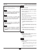
Pre-Installation Phase III® Recommended Clearances • Water heater should be installed to allow adequate clearance for servicing • • Zero clearance is permissible to either side of the TR and SMART Series water heater, but information labels may be hidden. • Recommended top or vertical clearance is 12” minimum.
Installation Phase III® Temperature & Pressure (T&P) Relief Valve NOTICE CAUTION Phase III® commercial water heaters will absorb less than 200,000 BTU/hr when domestic water outlet temperature is 210ºF and boiler water supply temperature is 240ºF. Listed outputs are based on ASME Section VIII Interpretation VIII-1-86-136. Check with local codes for applicability.
Installation Phase III® T&P Relief Valve Discharge Piping Commonwealth of Massachusetts Installation T&P relief valve discharge piping must be: • - made of material serviceable for temperatures of 250ºF or greater. Insert an open-end dip tube into the Auxiliary connection on top of water heater. • - directed so that hot water flows away from all persons. Install a 3/4” NPT elbow to the Auxiliary connection (Figure 3).
Installation Phase III® General Piping Water Hammer Dishwashers, clothes washers and fast-closing positive shut-off valves incorporated in the system all contribute to creating water shock. Install a water hammer arrester to prevent damage to pipes and appliances. See device manufacturer’s instructions for application and installation. • For domestic water piping diagrams, see page 8 thru 10. • See pages 11 through 14 for: - Boiler water piping - Multiple water heater domestic and boiler piping.
Installation Phase III® hot and cold water fittings from corrosion when connecting dissimilar materials such as copper and galvanized iron pipe. • If copper pipe is used for domestic water connections, first solder pipe to a threaded adapter and then screw adapter into cold water inlet on top of water heater. Inlet contains an internal plastic dip tube which can be damaged by heat from soldering. Do not apply heat to the cold water inlet when making sweat connections to water heater.
Installation - Piping Phase III® 12" min. Heat Trap Loop 1 1 5 13 H M 6 4 1 Cold Water Inlet 10 5 12" min. Heat Trap Loop C Standard Installation Domestic Piping TR Series 9 12" min. Heat Trap Loop 13 M 1 H 5 1 6 4 Cold Water Inlet 10 5 12" min. Heat Trap Loop C Standard Installation Domestic Piping SMART Series 1 9 Figure 1 1. 4. 5. 6. 9. Drain valve 10. Thermal expansion tank (potable) 13.
Installation - Piping Phase III® 12" min. Heat Trap Loop Recirculating Loop 3 2 1 4 1 5 Cold Water Inlet 1 6 10 5 12" min. Heat Trap Loop 11 Standard Installation Domestic Piping with Recirculation TR Series 9 12" min. Heat Trap Loop Recirculating Loop 3 2 5 4 1 6 1 Cold Water Inlet 10 1 5 12" min. Heat Trap Loop 11 Standard Installation Domestic Piping with Recirculation SMART Series 9 Figure 2 1. 2. 3. 4. 5. 6. Backflow preventer or pressure reducing valve(*) 9.
Installation - Piping Phase III® 12" min. Heat Trap Loop 4 13 M 1 5 6 8 1 Cold Water Inlet H 10 5 12" min. Heat Trap Loop C 11 Commonwealth of Massachusetts Domestic Piping TR Series 9 12" min. Heat Trap Loop 4 13 M 1 5 6 8 1 Cold Water Inlet H 10 5 12" min. Heat Trap Loop C 11 Commonwealth of Massachusetts Domestic Piping SMART Series 9 Figure 3 1. 4. 5. 6. 8. Shut-off valves T&P relief valve Unions Backflow preventer or pressure reducing valve Vacuum breaker 9.
Installation - Piping Phase III® 1 3- Port Priority Valve 2 12 SMART Series TR Series 7 11 Cold water inlet 1 1 9 Fig. 4: Phase III® System Piping with 3-Port Zone Valve (Domestic Priority) Note: See page 25 for TR Series Boiler Supply and Return Connections. 2-Port Priority Valve (normally open) 12 2 7 11 2-Port Priority Valve (normally close) 1 1 SMART Series Cold water inlet TR Series 9 Fig. 5: Phase III® System Piping with 2-Port Zone Valves (Domestic Priority) 1.
Phase III® Installation - Piping Zone Valve 1 Zone valve 2 12 SMART Series TR Series 7 Cold water inlet 1 11 1 9 Fig. 6: Phase III® System Piping with Zone Valves (Non Domestic Priority) 2 Note: See page 25 for TR Series Boiler Supply and Return Connections. 2 2 Zone Circulator 3 1 Zone Circulator SMART Series 12 7 TR Series 11 1 1 Cold water inlet 9 Fig. 7: Phase III® System Piping with Zone Circulators 1. 2. 3. 7.
Phase III® Installation - Piping T&P Relief Valve Fig. 8: Multiple TR Series Water Heater System Domestic Piping - Parallel Cold Water Inlet Isolation Valve Circulator Recirculated Water Automatic Mixing Valve Hot Water Outlet Cold Water Inlet • • • • Fig. 9: Multiple TR Series Water Heater System Domestic Piping - Series Recommended for most applications. Any one water heater tank thermostat may be utilized to control system temperature.
Installation - Piping Phase III® 3 2 12 7 Cold water inlet 1 11 1 Fig. 10: Multiple TR Series Water Heater System Boiler Piping 9 Reverse Return Balanced Flow 12 7 2 11 3 1 Cold water inlet 1 9 Fig. 11: Multiple TR Series Water Heater System Boiler Piping - Manifold 1. 2. 3. 7. Shut-off valves Circulator Flow check valve Expansion tank 9. Drain valve 11. Feed valve 12.
Installation Phase III® Circulators Wiring Requirements • WARNING Electrical shock hazard can cause severe personal injury, death or substantial property damage. Disconnect power before installing and/or servicing. Zone Valves • • Transformer must be sized for maximum load of all zone valves. Snap Set Connection 1. All wiring must be a minimum of 18 gauge and installed in accordance with: • Priority relay must be sized for total amp draw of all circulators. U.S.A.
Phase III® Installation - Wiring Fig. 13: Typical 3-wire Zone Valve Zoning, Fig. 12: Typical 4-wire Zone Valve Zoning, with Domestic Priority with Domestic Priority H 120 H V.A.C. High Voltage H 120 H V.A.C. High Voltage Transformer (Power) Transformer (Power) 24 V.A.C. 24 V.A.C.
Phase III® Installation - Wiring Fig. 15: Typical 3-wire Zone Valve Zoning, Fig. 14: Typical 4-wire Zone Valve Zoning, without Domestic Priority without Domestic Priority H 120 H V.A.C. High Voltage H 120 H V.A.C. High Voltage Transformer (Power) Transformer (Power) 24 V.A.C. 24 V.A.C.
Phase III® Installation - Wiring Fig. 16: Typical Circulator Zoning Fig.
Installation - Wiring Phase III® Fig. 18: Priority Zone Circulator Wiring Honeywell R845A Circulator Relay 120 H Thermostat zone 1 T T 2 1 VAC N Note: Maximum of 4 total circulator zone when wiring 1 zone for priority.
Water Heater Start-Up Phase III® Filling the Inner (Domestic Water) Tank NOTICE CAUTION • Never use water heater unless inner and outer tanks are completely filled with water. • Inner tank must be completely filled and pressurized before pressurizing outer tank. For proper operation of the water heater, always leave vent cap unscrewed one full turn. 6. If antifreeze is used in boiler water, check concentration.
Water Heater Start-Up Phase III® General Notes DANGER • Household water usage patterns will affect water temperature at any faucet or shower. Occasionally check temperature at each point of use, then adjust thermostat accordingly. Always recheck temperature after adjusting thermostat. • When hot water is used in repeated small quantities, a “stacking” effect can develop in the water heater. The upper layer of water in tank can be hotter than lower layer.
Water Heater Start-Up Phase III® Adjusting the Water Heater Thermostat • Check water temperature at a hot water faucet immediately after first heating cycle. Further temperature adjustment may be necessary as water heating system is used. Recheck water temperature at faucet after adjustment. • When adjusting thermostat, be sure boiler limit control is set a minimum of 20ºF higher. Water heater thermostat is factory set to its lowest temperature. This may or may not be suitable for your needs.
Water Heater Maintenance Phase III® Review homeowner’s maintenance responsibilities and their frequencies, including any not listed in the following section. Maintenance Schedule Annual service by qualified service technician should include the following: Homeowner monthly maintenance to include: Any procedure required by local codes. Check air vent operation. Check air vent operation. Verify system pressure.
Water Heater Maintenance Phase III® 2. Close system supply isolation valve. WARNING 3. Connect a hose to domestic water drain valve at cold water inlet. Hose should extend to drain at floor level to allow siphoning of domestic water tank. Do not use automotive, ethylene glycol or petroleum-based antifreeze. Do not use any undiluted antifreeze. This can cause severe personal injury, death or substantial property damage. 4. Open hot water faucet at highest point above heater. 5.
Phase III® Water Heater Specifications TR SERIES TR-20/30/36/80/100/120 Domestic Hot Water Outlet C Boiler Water Return (TR-20 thru TR-36) Boiler Water Supply (TR-45 thru TR-120) D E 2" Auxiliary Connection 1/2" NPT Air Vent Drywell for Remote Sensing Bulb TR-45/60 C Auxiliary Connection 4 1/8" F D 4 1/8" E Domestic Hot Water Outlet B A Domestic Cold Water Inlet Boiler Water Supply (TR-20 thru TR-36) Boiler Water Return (TR-45 thru TR-120) Drywell for Remote Sensing Bulb 1/2" NPT Air
Water Heater Specifications Phase III® SMART SERIES Auxiliary Connection Cold Water Inlet Specifications Hot Water Outlet Air Vent Boiler Return Cold Water Inlet C A 22" Hot Water Outlet B Boiler Supply Thermostat Cover Plate 14 1/4" Auxiliary Connection 22" Rear view SMART-20/30/40/50/60 Top view SMART-20/30/40/50/60 Auxiliary Cold Water Inlet Thermostat & Drywell Hot Water Outlet A Boiler Return C Air Vent Hot Water Outlet Cold Water Inlet Boiler Supply B Auxiliary Connection
Performances Phase III® Model TR-20 TR-30 TR-36 TR-45 TR-60 TR-80 TR-100 TR-120 Model SMART SMART SMART SMART SMART SMART SMART 20 30 40 50 60 80 100 Boiler Heating Capacity MBH Peak Flow Gal./10 min. 1st Hour Flow Gal./Hour Continuous Flow Gal./Hour Circulator Min. GPM 80 87 118 137 270 337 375 420 35 45 55 70 110 135 160 190 125 140 190 220 410 510 575 650 110 115 160 185 360 450 500 560 5 6 8 9 18 22 25 28 Boiler Heating Capacity MBH Peak Flow Gal./10 min. 1st Hour Flow Gal.
Phase III® Replacement Parts List SMART Series TR Series Code P3AVT01 P3KITTH01 P3BP01 P3BP02 P3BP03 P3BP04 P3CS01 P3CS02 P3CS03 P3CS05 P3CS04 P3DT02 P3DT04 P3DT10 P3DT05 P3DT06 P3DT08 P3DT09 P3DNK01 P3DWT01 P3DWT02 P3DWT04 P3DWT02 P3DWT03 P3DWT04 P3DWT04 P3DWT04 P3JKT20F P3JKT30F P3JKT36F P3JKT45F P3JKT60F P3JKT75F P3JKT100F P3JKT120F P3JKT20B P3JKT30B P3JKT36B P3JKT45B P3JKT60B P3JKT75B P3JKT100B P3JKT120B P3JKT20L P3JKT30L P3JKT36L P3JKT45L P3JKT60L P3JKT75L P3JKT100L P3JKT120L P3JKT20R P3JKT30R P3JKT3
Sample Specifications Phase III® TR_______or equal SMART_______or equal 1. Hot water tank designed for production of domestic hot water using hot water as heating source. The principle consists of two concentric tanks. The inner tank contains domestic hot water and the outer tank contains heating system water. The inner tank shall have a capacity of ________gallons. 1. Hot water tank designed for production of domestic hot water using hot water as heating source.
Additional quality water heating equipment available from: Triangle Tube/Phase III Phase III HM Series Water Heaters - Stainless steel construction Oil and Gas fired A unique design that eliminates the problem of scaling found with traditional water heaters Inputs ranging from 100,000 BTU/hr to 382,000 BTU/hr Capable of 180º continuous production 10 year non-prorated warranty ETL Laboratories listed ASME version available TTP Brazed Plate Heat Exchangers - For domestic water, snow melting, radiant floo