600 mm Built In Oven OPERATING AND INSTALLATION INSTRUCTIONS MODEL NO.
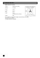
TECHNICAL DETAILS MODEL NO. BS 631/2 / BS 641 Voltage: 230/240 Volts AC 50Hz Wattage: 2.7/2.9kW Height: 595mm Width: 595mm Depth: 545mm (excluding handles and knobs) Weight: 30kg These appliances comply with: European Council Directive 73/23/EEC. EMC Directive 89/336/EEC. CE Marking Directive 93/68/EEC.
CONTENTS Please follow these instructions step by step to install and operate your oven safely and easily. Technical Details . . . . . . . . . . . . . . . . . . . . . . . . . . . . . . . . . . . . . . . . . . . . . . . . . . . . . . . . . . . . . . . . . . . . . . . 2 Contents . . . . . . . . . . . . . . . . . . . . . . . . . . . . . . . . . . . . . . . . . . . . . . . . . . . . . . . . . . . . . . . . . . . . . . . . . . . . . . . 3 Preface . . . . . . . . . . . . . . . . . . . . . . . . . . . . . . . . .
The Fan Oven . . . . . . . . . . . . . . . . . . . . . . . . . . . . . . . . . . . . . . . . . . . . . . . . . . . . . . . . . . . . . . . . . . . . . . . . . 26 Uses of the Fan Oven . . . . . . . . . . . . . . . . . . . . . . . . . . . . . . . . . . . . . . . . . . . . . . . . . . . . . . . . . . . . 26 Selecting the Fan Oven . . . . . . . . . . . . . . . . . . . . . . . . . . . . . . . . . . . . . . . . . . . . . . . . . . . . . . . . . . 26 Things to Note . . . . . . . . . . . . . . . . . . . . . . . . .
PREFACE Dear Customer, Thank you for buying a Tricity Bendix built-in oven. With our 80 years experience in developing and manufacturing the very best in U.K. cookers, you can be assured that you have purchased a hard working, reliable, quality cooker. In addition Tricity Bendix cookers comply with British Standard safety and performance requirements. They have been approved by BEAB (British Electrotechnical Approvals Board) and are covered by a 12 month parts and labour guarantee.
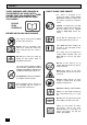
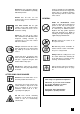
SAFETY THESE WARNINGS ARE PROVIDED IN THE INTERESTS OF YOUR SAFETY. ENSURE THAT YOU UNDERSTAND THEM ALL BEFORE INSTALLING OR USING THE COOKER. PLEASE READ CAREFULLY BEFORE INSTALLING YOUR COOKER This cooker is heavy and care must be taken when moving it. Ensure that all packaging, both inside and outside the cooker has been removed before the cooker is used. Do not try to move the cooker by pulling the door handle. Refer to installation instructions.
Cookers and hobs become very hot, and retain their heat for a long period of time after use. Children should be kept well away from the cooker until it has cooled. Ensure that you support the grill pan when it is in the withdrawn or partially withdrawn position. Ensure that all vents are left unobstructed to ensure ventilation of the oven cavity.
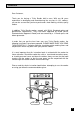
INSTALLATION INSTRUCTIONS THINGS YOU NEED TO KNOW GETTING THINGS READY WARNINGS: CHOICE OF ELECTRICAL CONNECTION l l This cooker must be installed by a qualified electrician/competent person. Safety may be impaired if installation is not carried out in accordance with these instructions. l l This cooker must be earthed. Do not remove the screws from the earth tab extending from the oven mains terminal block (Fig. 8).
ii) By connecting the cooker point to the hob and then connecting the hob to the oven. Provided that the hob manufacturer permits it, connect the oven to the hob and the hob to the cooker point using the same cabling as described in (a) above. Check the hob terminal block is large enough to take two cables and is of suitable rating. If not b) i) on page 8 must be used. See Fig. 2. NOTE: 13 Amp cable is not suitable for connecting this application. Fig.
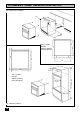
RECOMMENDED CABINET DIMENSIONS (IN MILLIMETRES) Fig. 3 Built Under Installation. 600 560 min 570 max Cross section through cabinet showing oven positioned 600 595 600 min 2000 Recommended 540 540 5 5 585 595 570 5 5 Cross section through cabinet showing oven positioned 570 550 min 560 min 570 max 550 min Fig. 4 Built In Installation.
HOW TO FINISH UNPACKING l l l l Place packed cooker next to the cabinet in which it will be installed. Carefully score down from each end of the cable sheathing along the length of the bare earth wire (if a cut was made along the length of the live and neutral wires, it might cut into their sheathing) to the cuts already made. Remove the cooker packing except for bottom tray which should be left in position until the cooker is ready to be fitted into its cabinet.
l Lift cover and remove screw from cable clamp. See Fig. 7. l l Cable Clamping Block Fig. 7 Clamp the mains cable securely ensuring 5mm of the outer insulation is inside the terminal block and that the wires are not taught but not so slack as to cause any fouling. See Fig. 8. Place fuse/miniature circuit breaker in circuit and switch on at mains. CONNECTING TO A HOB OR COOKER POINT Feed the cable through the cabinet and arrange to route the cable away from the cooker which may become hot.
FITTING INTO THE CABINET IMPORTANT: Ensure that the oven is switched off at the wall before any further work is carried out. Using a tape measure establish the internal width of the cabinet. Refer to page 9 if greater than 565mm. l l l Position the cooker in front of the cabinet. See Fig. 9. Take out all oven furniture before installation to reduce the weight you need to lift. The oven door should be taped up to keep it closed whilst lifting. Fig.
INTRODUCTION WARNING: THIS COOKER MUST BE EARTHED GETTING TO KNOW YOUR OVEN (BS 631/2) A B E D F C A- Electronic Timer E- Selector B- Oven Indicator Neon Fan Oven C- Grill Indicator Neon Conventional Oven D- Oven Temperature Control Zoned Oven Defrost Oven Clean Thermal Grill Dual Grill F- Dual Grill Control GETTING TO KNOW YOUR OVEN (BS 641) A B D E A- Electronic Timer C- Oven Temperature Control B- Selector D- Dual Grill Control Fan Oven E- Oven Indicator Neon Convention
RATING PLATE COOKWARE Record the model, product and serial numbers on the back cover of this instruction book from the rating plate. This is situated on the lower front frame of the cooker and can be seen upon opening the oven door. Baking trays, oven dishes etc., should not be placed directly against the grid covering the fan at the back of the oven. Do not use baking trays larger than 30cm x 35cm (12" x 14") as they will restrict the circulation of heat and may affect performance.
THE SHELF POSITIONS Recommended shelf positions have been shown in the cooking chart on page 32. If not fitted correctly the shelf will lie at an angle and the safety stop will not be effective. To ensure that the shelf has the correct side uppermost, the wire stringers, which make up the shelf, should lie on top of the surrounding frame. GRILL AND OVEN FURNITURE The following items of grill and oven furniture have been supplied with the cooker.
THE TIMER (BS 631/2) Please note that this is a 24 hour clock, for example 2.00 pm is shown as 1400. Cookpot symbol Bell symbol In the following pages we explain how to set the controls. Read through them a few times until you are familiar with the procedure. If the oven is switched off on the wall, or there is a loss of power, the clock will stop and you will not be able to use the oven. When you first switch the electricity supply on, the timer display will flash.
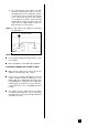
SETTING THE CONTROLS FOR AUTOMATIC USE This is very easy. All you have to do is work through the steps below. The clock will work out the rest for itself. 1 Is the electricity supply on? 2 Is the clock showing the To adjust turn the selector knob correct time? to 'manual' then turn to 'clock'. Turn the setting knob in either direction. 3 How long will the food take to cook? Turn the selector knob to 'cook'. Then turn the setting knob until the length of time you want the food to cook shows in the display.
THE TIMER (BS 641) KEY A AUTO DISPLAY B MINUTE MINDER BUTTON C COOKING HOURS BUTTON D STOP TIME BUTTON E COOKING SYMBOL F MANUAL SELECTOR BUTTON G DECREASE CONTROL H INCREASE CONTROL NOTE: Step 1 must be completed before the oven will operate manually. 1. SET THE TIME OF DAY When the electricity supply is first switched ON, the display will flash both 0.00 and AUTO as Fig.1. Fig.
Release the minute minder button and the display will return to the time of day after 5 seconds. During the operation of the minute minder, the remaining time period can be shown in the display by pressing the minute minder button ( ) as Fig. 5. Fig. 5 The minute minder will sound intermittently, for up to 2 minutes and the bell symbol will flash at the end of the timed period. The sound can be stopped by pressing any of the 4 left hand side buttons. 3.
Note: When the automatic timed period starts, the oven indicator neon will cycle ON and OFF during cooking. B) TO SET THE TIMER TO SWITCH OFF ONLY i) Ensure the electricity supply is switched ON and that the correct time of day is displayed, e.g. 10.00 a.m. as Fig. 9. Fig. 9 ii) Place food in oven. iii) To set the length of cooking time, press the cooking hours button ( ) depress the increase control ( + ) until the required length of cooking time is displayed, e.g. 2 hrs 15 mins as Fig. 10.
5. THINGS TO NOTE The time of day cannot be altered whilst the AUTO symbol is lit. During the hours of 10p.m. (22.00hrs.) and 6 a.m. the display will glow dim. If a function is selected the display will glow brighter until the function is complete. It will then revert back to the dim mode. A programme may be cancelled by returning the cooking hours to zero. Press the cooking hours button ( ) press ( - ) button until 0.00 is displayed as Fig. 14. Release all buttons.
THE GRILL USES OF THE GRILL CAUTION - ACCESSIBLE PARTS MAY BECOME HOT WHEN THE GRILL IS IN USE. CHILDREN SHOULD BE KEPT AWAY. The grill is a dual circuit grill which means that the full area of the grill can be used or for economy purposes the centre section only can be used when cooking smaller quantities of food. SELECTING THE GRILL BS 631/2 l l l Set the selector to dual grill. Turn the grill control clockwise for full grill or anticlockwise for the centre section only.
THE GRILL PAN AND HANDLE The grill pan is supplied with a removable handle. To check the progress of the food being grilled, the grill pan should be withdrawn on the shelf to attend to food during cooking. To insert the handle, press the button on the handle with the thumb and pivot the handle slightly upwards inserting the lip into widest part of the bracket. Move the handle towards the left, lower into position and release the button. Ensure the handle is positively located.
l l l l l l Food should be thoroughly dried before grilling to minimise splashing. Brush lean meats and fish lightly with a little oil or melted butter to keep them moist during cooking. Accompaniments such as tomatoes and mushrooms may be placed underneath the grid when grilling meats. When toasting bread, we suggest that the top runner position is used with the grid in its 'low' position. Preheat the grill on a full setting for a few minutes before sealing steaks or toasting.
THE FAN OVEN USES OF THE FAN OVEN The oven is heated by the element around the fan situated behind the back panel. The fan draws air from the oven, the element heats the air which is circulated into the oven via the vents in the back panel. The advantages of fan oven cooking are: PREHEATING The fan oven quickly reaches its temperature, so it is not usually necessary to preheat the oven. Without preheating, however, you may find you need to add an extra 5-10 minutes on the recommended cooking times.
l THINGS TO NOTE 1. The temperature control and selector indicator windows will illuminate (BS 641). 2. The oven indicator neon will glow until the oven has reached the desired temperature and then go out. It will cycle ON and OFF periodically during cooking showing that the temperature is being maintained.
THE CONVENTIONAL OVEN USES OF THE CONVENTIONAL OVEN This function uses the top and lower elements to give single level cooking. This is particularly suitable for dishes which require extra base browning such as pizzas, quiches and flans. Gratins, lasagnes and hotpots which require extra top browning also cook well in the conventional oven. This form of cooking gives you the oppurtunity to cook without the fan in operation. SELECTING THE CONVENTIONAL OVEN BS 631/2 l Turn the selector to Conventional Oven.
HINTS AND TIPS l l l l l The middle shelf position allows for the best heat distribution. To increase base browning simply lower the shelf position. To increase top browning, raise the shelf position. l l For faster preheating use the fan oven function to preheat the oven until the oven indicator neon goes out, then switch the selector to the conventional oven setting. Single level cooking gives best results. If you require more than one level cooking use the fan or zoned oven functions.
THE ZONED OVEN USES OF THE ZONED OVEN When the Zoned Oven is selected the top oven element operates in conjunction with the fan with effect that the top of the oven is hotter than the bottom. As there is a difference of up to 30°C between the top and bottom of the oven this feature is especially useful for dishes requiring different temperatures at the same time, making it ideal for cooking a complete meal on two shelves. SELECTING THE ZONED OVEN BS 631/2 l Turn the selector to Zoned Oven.
HINTS AND TIPS l l l l Remember that the top of the oven is hotter than the bottom. The approximate difference in temperature between the top and the bottom is 30°C. If a higher shelf position is used than is recommended in the chart on page 32 it may be necessary to lower the cooking temperature by approximately 10°C. Be prepared to interchange dishes between the higher and lower shelf position during cooking, where necessary.
OVEN COOKING CHART The oven temperatures are intended as a guide only. It may be necessary to increase or decrease the temperatures by 10°C to suit individual preferences and requirements. NOTE: Shelf positions are counted from the bottom of the oven.
THERMAL GRILLING USES OF THERMAL GRILLING Thermal grilling offers an alternative method of cooking food items normally associated with conventional grilling. The grill element and the oven fan operate together, circulating hot air around the food. The need to check and turn food is reduced. Thermal grilling helps to minimise cooking smells in the kitchen and allows you to grill with the oven door closed.
THINGS TO NOTE l 1. The oven indicator neon will glow until the oven has reached the desired temperature and then go OFF. It will then cycle ON and OFF showing that the oven temperature is being maintained. Accompaniments such as tomatoes and mushrooms may be placed below the grid when grilling meats, or in a separate dish on a lower shelf. 2. The indicator windows for selector and oven temperature control will illuminate (BS 641). 3. The oven fan and internal light will come on. 4.
THERMAL GRILLING CHART FOOD SHELF TEMP (°C) TIME (mins in total) Bacon Rashers Beefburgers Chicken Joints Chops - Lamb - Pork Fish - Whole Trout - Mackerel Fillets - Plaice/Cod Kebabs Kidneys - Lamb/Pig Liver - Lamb/Pig Sausages Steaks - Medium 3 3 4 4 4 4 4 3 3 3 3 3 3 200 190 160 170 170 170 170 170 170 180 180 190 220 Steaks - Well Done Heating through and Browning e.g.
DEFROST FEATURE USES OF DEFROST FEATURE This function enables you to defrost most foods faster than some conventional methods as the oven fan circulates air around the food. It is particularly suitable for delicate frozen foods which are to be served cold e.g. cream filled gateaux, cakes covered with icings or frostings, cheesecakes, biscuits, scones etc. Small or thin fish fillets, frozen peeled prawns, cubed or minced meat, liver, thin chops, steaks etc., can be thawed in 1 - 2 hours.
THINGS TO NOTE 1. The selector indicator window will illuminate (BS 641). 2. The oven fan and internal oven light will come on. No heat is produced when the defrost function is selected. The heating elements stay OFF even if the temperature control is set. 3. The cooling fan for the controls should not operate. 4. Care must always be taken when handling foods in the home.
HELPFUL HINTS WHEN BUYING AND PREPARING FOOD Care must be taken when handling foods in the home. Always follow the basic rules of food hygiene to prevent bacterial and microbial growth and cross contamination when preparing, reheating, cooking, cooling, defrosting and freezing foods. 10. Cook meat thoroughly - use a meat thermometer if preferred, which penetrates the joint to check that the centre temperature has reached the required temperature (see table below). MEAT 1.
OVEN CLEAN FEATURE USES OF OVEN CLEAN FEATURE During normal use the Stayclean coating within the oven will become splashed with fats and food residues. When the oven clean feature is selected the Stayclean surfaces burn off any soilage. See Care of Stayclean Surfaces on page 42 for more details. Regular use of the oven clean function will keep the Stayclean panels in good condition. SELECTING OVEN CLEAN BS 631/2 l Remove oven shelves and bakeware from oven. l Turn the selector to oven clean.
HINTS AND TIPS l Manual cleaning of the Stayclean surfaces is NOT recommended. Damage will occur if soap impregnated steel wool pads, aerosol cleaners, or any abrasive cleaners are used. l l l l l Slight discolouration and polishing of the Stayclean surfaces may occur in time, but this will not affect their self cleaning properties. Use the oven clean function for an hour or two per week to avoid a build up of soilage which could prevent the Stayclean enamel from working properly.
CARE AND CLEANING BEFORE CLEANING THE COOKER ALWAYS ALLOW THE COOLING FAN TO COOL THE COOKER DOWN BEFORE SWITCHING OFF THE ELECTRICITY SUPPLY. CLEANING BETWEEN THE OUTER AND INNER DOOR GLASS The outer door glass is removable for cleaning. TO REMOVE THE OUTER GLASS CLEANING MATERIALS Before using any cleaning materials on your cooker, check that they are suitable and that their use is recommended by the manufacturer. Cleaners that contain bleach should NOT be used as they may dull the surface finishes.
TO CLEAN INSIDE THE INNER GLASS DOOR HINTS AND TIPS The inner glass door is not removable. Clean using hot soapy water or Hob Brite and a soft cloth. Take care NOT to use abrasives as they may damage the glass or seal. l CLEANING INSIDE THE OVEN The Stayclean surfaces inside the oven should not be cleaned manually. See 'Care of Stayclean Surfaces' below. The vitreous enamel on the oven base can be cleaned using normal oven cleaners or aerosol oven cleaners with care.
REPLACING THE OVEN LIGHT BULB The type of bulb required is a 300C 25 watt small Edison Screw. Part number 572 491 5431-00/1. (Available through Tricity Bendix service centres). CAUTION: DISCONNECT THE COOKER FROM THE ELECTRICITY SUPPLY BEFORE REPLACING THE BULB. Open the oven door and remove the shelves to enable easy access to the oven light assembly. Insert a flat blade screwdriver between the oven side and the glass which covers the bulb.
SOMETHING NOT WORKING Please carry out the following checks on your cooker before calling a Service Engineer. It may be that the problem is a simple one which you can solve yourself without the expense of a Service call. The oven temperature is too high or low. * Check that the recommended temperatures are being used (see page 32). Be prepared to adjust up or down 10°C to achieve the results you want. * The grill, oven and timer do not work.
SERVICE AND SPARE PARTS HELP US TO HELP YOU Please determine your type of enquiry before writing or telephoning. SERVICE Before calling out an Engineer, please ensure that you have read the details under the heading 'Something Not Working?' and have the model number and purchase date to hand. The model, product and serial numbers, which should be quoted in any communication can be found on the rating plate on the lower front frame of the cooker upon opening the oven door.
TRICITY BENDIX SERVICE CENTRES To contact your local Tricity Bendix Service Centre telephone 0990 929929 ORKNEY (M65) SCOTLAND ABERDEEN (M05) AUCHTERMUCHY (M03) ARGYLL (M67) 8 Cornhill Arcade Cornhill Drive Aberdeen AB2 5UT 33A Burnside Auchtermuchy Fife KY14 7AJ Briar Hill 7 Hill Street, Dunoon Argyll PA23 7AL BLANTYRE Unit 5 (M07) Block 2 Auchenraith Industrial Estate Rosendale Way Blantyre SHETLAND (OWN SALES) SHETLAND (OWN SALES) SHETLAND (OWN SALES) WHALSAY (OWN SALES) Refrigeration Sales &
TRICITY BENDIX SERVICE CENTRES To contact your local Tricity Bendix Service Centre telephone 0990 929929 MIDLANDS BIRMINGHAM (M18) 66 Birch Road East, Wyrley Road Industrial Estate Witton Birmingham B67DB BOURNE Manning Road Ind Estate (M44) Pinfold Road Bourne PE10 9HT GLOUCESTER 134 Eastgate Street (M23) Gloucester GL1 1QT HEREFORD Unit 3 (M31) Bank Buildings Cattle Market Hereford HE4 9HX HIGHAM FERRERS The Old Barn (M51) Westfield Terrace Higham Ferrers NN10 8BB ILKESTON Unit 2 (M43) Furnace Road Ilkes
GUARANTEE CONDITIONS We, Tricity Bendix, undertake that if within 12 months of the date of the purchase this Tricity Bendix appliance or any part thereof is proved to be defective by reason only of faulty workmanship or materials, we will, at our option repair or replace the same FREE OF ANY CHARGE for labour, materials or carriage on condition that: l l l l l l 48 The appliance has been correctly installed and used only on the electricity supply stated on the rating plate.
BS 631/2 - BS 641-311240409
RATING PLATE REFERENCE MAKE AND MODEL NO. SERIAL NO. PRODUCT NO. DATE OF PURCHASE IMPORTANT NOTICE In line with our continuing policy of research and development, we reserve the right to alter models and specifications without prior notice. This handbook is accurate at the date of printing, but will be superseded and should be disregarded if specifications or appearance are changed. TRICITY BENDIX,PO BOX 47,NEWBURY,BERKSHIRE, RG14 5XL TELEPHONE (01635) 525542 4 MODEL NO. PART NO.