TRINITY BENDIX E L T Better Products. Better Value.
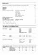
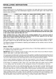
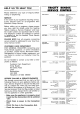
CONTENTS Firebase refer to the sections in this bookie that apply to your particular model; CONTENTS WARNINGS GENERAL INSTALLATION INSTRUCTIONS OPERATING INSTRUCTIONS DO'S AND DON'TS MAINTENANCE AND CLEANING MAINTENANCE AND CLEANING HELP US TO HELP YOU ELECTRICAL CONNECTION UNPACKING POSITIONING WALL FITTING WALL CABINET FITTING DUCTING FITTING WORKTOP LIGHTING FILTERS TRINITY BENDIX SERVICE CENTERS Page @O MmN ND DG RN TECHNICAL SPECIFICATIONS DIMENSIONS CH520 Width om 49.8 CHUB Width om 59.8 Height om 15.
WARNINGS 1t is most important that this instruction book should he retained with the appliance for suture reference. Should the appliance be sold or transferred to another owner, or should you move house and leave the appliance always ensure that the book is supplied with the appliance In order that the new owner can be acquainted with the functioning of the appliance and the relevant warnings.
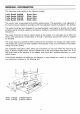
GENERAL INFORMATION This instruction book applies to the following models: Trinity Bendix CH520B Brown 50cm ‘Trinity Bendix CH520W White 50cm Trinity Bendix CH6108 Brown 60cm Trinity Bendix CHEW White 60cm This cooker hood is guaranteed and will give lasting service.
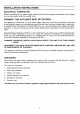
INSTALLATION INSTRUCTIONS ELECTRICAL CONNECTION Before connecting to the mains supply ensure that the mains voltage corresponds to the voltage on the rating plate inside the cooker hood. WARNING: THIS APPLIANCE MUST BE EARTHED. This appliance is fitted with a 3 core mains supply cable and should be permanently connected o the electricity supply via a double-pole switch having 3mm minimum contact gap on sate pole. A Switched Fuse Connection Unit to BS.
INSTALLATION INSTRUCTIONS POSITIONING When installing above a Trinity Bendix hob (as specified in the table below) the minimum distance between the surface of the hob dismantlement supports and the lower grills of the cooker hood must be 60cm (23 5/87). MODEL FRONT LEFT | REAR LEFT | REAR RIGHT [FRONT RIGHT| TOTAL HS 100 Electric 1.5Kw 0K 20w 15Kw 6.0Kw HG 211 Gas 3.0Kw 2,0Kw 2.0Kw 1.0Kw 8.0Kw HG 215 Gas 3.0Kw 2.0Kw 2.0Kw 1.0Kw 8.0Kw HG 240 Gas 3.0Kw 2.0Kw 2.0Kw 1.0Kw 8.0Kw HC 312 Ceramic 1.7Kw 1.2Kw 1.
INSTALLATION INSTRUCTIONS Access to the two wall leveling screws and the security fixing system will require the removal of the lower inter grille that supports the grease mat filter. To remove the lower grille press inwardly on the two slide catches located towards either side of the grille near the front and the grille will ops from the front. The grille pivots at the rear. Slide the right edge of the grille forward until it clears the guide and then unhook the left hinge pin.
OPERATING INSTRUCTIONS The cooker hood functions are controlled by two slide switches and a change-over slider control The two slide switches, which are located on the right hand side in the front fascia panel, control the fan speed and worktop illumination. The change-over slider control is located inside the cooker hood behind the inlet grille immediately in front of the lamp assembly. Ensure the hood is plugged in, or wired in and the power supply is switched on.
MAINTENANCE AND CLEANING DISCONNECT THE HOOD FROM THE MAINS SUPPLY BEFORE CARRYING OUT ANY KIND OF MAINTENANCE OR CLEANING. WORKTOP LIGHTING if a lamp fails to function at any time first check that it is fully screwed into the holder. When changing the damp an identical replacement must be fitted to ensure the safe working of the cooker hood. Replacement lamps are specified 230-volts Watt clear cylindrical, candle, or tulip shape with small Edison {E14) screw thread cap.
Rating Plate The rating plate is situated inside the casing on the back panel. It gives the MODEL AND SERIAL NUMBER, which should be quoted in any communication or if the service department is contacted. it is advisable to make a note of these below and keep for reference before the appliance is linseed. MAKE AND: MODEL NGO, SERIAL NO.