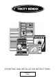
OPERATING AND INSTALLATION INSTRUCTIONS MODEL NO.
IMPORTANT SAFETY INFORMATION These warnings are provided in the interests of your safety. Ensure that you understand them all before installing or using the cooker. Your safety is of paramount importance. If you are unsure about any of the meanings of these warnings contact the Customer Care Department. The address is on the back page of this book. INSTALLATION l Stand clear when opening the drop down l The cooker must be installed according to oven doors.
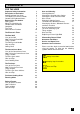
CONTENTS FOR THE USER Important Safety Information Description of the Cooker Getting to Know Your Oven The Cooling Fan for the Controls Control Panel Indicator Neons Before Using The Cooker Rating Plate When First Switching On Condensation and Steam Cookware The Trivet Grill and Oven Furniture 2 5 6 7 7 8 8 8 8 9 9 10 The Electronic Timer 11 The Dual Grill Uses of the Grill How To Use the Dual Grill Things To Note The Grill Pan and Handle Hints and Tips Grilling Chart 15 15 15 15 16 16 18 The Convenie
FOR THE INSTALLER Technical Details Things You Need to Know Warnings Choice of Electrical Connection 40 41 41 41 Things to Note Preparing Cabinet for Fitting Oven How to Finish Unpacking 42 43 44 Making the Electrical Connections To Remove Cover of Mains Terminal Connecting to the Mains Terminal Checking Electrical Connections Connecting to a Hob or Cooker Point 45 45 46 47 47 .
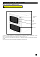
DESCRIPTION OF THE COOKER Built in electric double oven WARNING: THIS COOKER MUST BE EARTHED Electronic Timer Dual Grill Convenience Oven Fan Oven Your built in cooker comprises of a conventional oven and dual grill in the top compartment. The top oven is convenient and economical for mid-week use because of its size. The main fan oven is the larger of the two ovens. It is particularly suitable for cooking larger quantities of food.
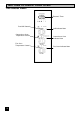
GETTING TO KNOW YOUR OVEN The Control Panel Electronic Timer Dual Grill Control Grill Indicator Neon Convenience Oven Temperature Control Fan Oven Temperature Control 6 Convenience Oven Indicator Neon Fan Oven Indicator Neon
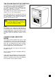
THE COOLING FAN FOR THE CONTROLS Your cooker has a cooling fan fitted behind the controls to prevent them from overheating. The cooling fan will come on immediately when the grill is switched on and after a short time when either of the ovens are in use. The cooling fan may cycle on and off when the cooker is in use. This is quite normal. The cooling fan may run on after the ovens or grill are switched off for a period of time to cool the cooker down.
BEFORE USING THE COOKER WHEN FIRST SWITCHING ON The timer must be set to manual operation before the fan oven can be operated. This must be done whenever the cooker is switched off at the wall or when there has been a power failure. For instructions on how to set the timer see page 11. If the Fan oven indicator neon does not glow when the oven controls are switched on, it is most likely that the timer is set for automatic cooking.
COOKWARE Baking trays, dishes etc., should not be placed directly against the grid covering the fan at the back of the oven. Do not use baking trays larger than 30cm x 35cm (12" x 14") as they will restrict the circulation of heat and may affect performance. Advice on the effect of different materials and finishes of bakeware is given in 'Hints and Tips' in the appropriate oven section. THE TRIVET When roasting we recommend that you use the trivet in the meat tin.
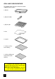
GRILL AND OVEN FURNITURE The following items of oven furniture have been supplied with the cooker. 1 grill pan 1 grill pan handle 1 grill pan grid 1 trivet 1 meat tin 2 shelves for Fan oven cooking 1 shelf for grilling and Convenience oven cooking Scuffing of the Stayclean sides and back panel by the oven furniture pack may occur during transit. These marks will disappear after the oven has been used for the first time.
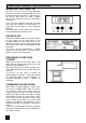
THE ELECTRONIC TIMER The electronic timer can indicate the time of day, operate as a minute minder and automatically time the fan oven. A Auto Symbol ( automatic cooking ) Bell Symbol ( minute minder ) Cookpot Symbol ( manual cooking ) Cookpot Symbol Auto Symbol Bell Symbol Please note that this is a 24 hour clock, for example 2pm is shown as 14.00. If the oven is switched off at the wall or there is loss of power the clock will stop and you will not be able to use the cooker.
AUTOMATIC TIMER CONTROL The automatic timer can be used with the fan oven only. TO SWITCH THE FAN OVEN ON AND OFF AUTOMATICALLY 1. Ensure the clock is showing the correct time of day. 2. Place food in the fan oven. 3. Set the length of time you want the food to cook for by pressing and releasing the button and then pressing the + button until the correct cooking time is displayed. This must be completed within 5 seconds of pressing the button. The maximum cooking time is 23 hours 59 minutes.
5. Turn the fan oven control to the correct temperature. The clock will work out what time the oven will switch itself on and will switch the oven off at the end. An audible signal will sound when cooking is complete. To cancel the sound, see below. RETURNING THE COOKER TO MANUAL OR TO CANCEL AN AUTOMATIC PROGRAMME Once automatic cooking is complete an alarm will sound and the Auto symbol will flash to remind you that the oven needs to be set for manual operation. 1. To do this press buttons and together.
At the end of the cooktime the oven will switch off, the alarm will sound and the auto symbol will flash. 5. To cancel and return to manual operation press buttons and together. 6. Turn off the oven temperature control.
THE DUAL GRILL WARNING - Accessible parts become hot when the grill is in use. Keep children away. USES OF THE GRILL The grill is situated in the Convenience oven compartment. The grill is a dual circuit grill which means that the full area of the grill or the centre section only can be used. Use the full grill for cooking larger quantities of food. Use the centre section for economy purposes when cooking smaller quantities. DUAL GRILL HOW TO USE THE DUAL GRILL 1. Open the Grill / Convenience Oven door.
THE GRILL PAN AND HANDLE The grill pan has a removable handle. To insert the handle, press the button on the handle with the thumb and pivot the handle slightly upwards inserting the lip into widest part of the bracket. Move the handle towards the left, lower into position and release the button. Ensure the handle is positively located. To remove the handle, press the button on the handle with the thumb and pivot the handle slightly upwards and towards the right to remove from the bracket.
The grill pan grid is reversible. This is useful if you want to cook foods of varying thickness. As a general rule, bread for toasting should be placed on the grid in the ' high ' position in the grill pan. Foods such as chicken pieces or chops may be grilled using the grilling grid in the low position. Food should be thoroughly dried before grilling to minimise splashing. Brush lean meats and fish lightly with a little oil or melted butter to keep them moist during cooking.
GRILLING CHART The chart below gives recommended cooking times and shelf positions. Remember that these are a guide and should be adjusted to suit personal taste. Note Shelf positions are counted from the bottom upwards.
THE CONVENIENCE OVEN USES OF THE CONVENIENCE OVEN The Convenience oven is the smaller of the two ovens. The Convenience oven is a conventional oven, i.e. without a fan. It is convenient where smaller quantities or convenience foods are being cooked. It is important to refer to the cooking chart as a guide to shelf positions and temperatures as these may differ from previous cookers you may have used. CONVENIENCE OVEN HOW TO USE THE CONVENIENCE OVEN 1.
HINTS AND TIPS Use the convenience oven when you want to warm plates. Use a setting of 80°C - 100°C on the oven temperature control. You can only cook on one shelf when using the Convenience oven. For the best results food should be placed in the centre of the oven. To increase top browning e.g. for au gratin dishes, the food should be placed towards the top of the oven. Similarly for foods which benefit from the base being browned, e.g. pizza, quiches and flans place the food on a lower shelf.
When roasting we recommend that you use the trivet in the meat tin. Fat and meat juices will drain into the meat tin below and can be used to make gravy. The trivet also prevents splashes of fat from soiling the oven interior. Note. The meat tin should not be placed on a heated hotplate as this may cause the enamel to crack. CONVENIENCE OVEN COOKING CHART Note: Shelf positions are counted from the bottom upwards.
THE FAN OVEN USES OF THE FAN OVEN The Fan oven is particularly suitable for cooking larger quantities of food or for weekend or celebration meals. The advantages of Fan oven cooking are: PREHEATING The Fan oven quickly reaches its temperature so it not usually necessary to preheat the oven. Without preheating however you may need to add an extra 5 - 10 minutes on the recommended cooking times. For recipes needing high temperatures e.g. bread, pastries, scones, soufflés etc.
TO FIT THE FAN OVEN SHELVES The shelves should be fitted with the straight rods uppermost on the frame and the forms towards the back of the oven. If not fitted correctly the anti-tilt and safety stop mechanism will be affected. HINTS AND TIPS Back of the oven Straight Rods Frame 14 Arrange the shelves in the required positions before switching the oven on. Shelves are numbered from the bottom upwards.
FAN OVEN COOKING CHART The oven temperatures are intended as a guide only. It may be necessary to increase or decrease the temperatures by a further 10°C to suit individual preferences and requirements. Note: Shelf positions are counted from the bottom of the oven.
ROASTING CHART ROASTING CHART INTERNAL TEMPERATURES Rare: 50 - 60°C; Medium: 60 - 70°C; Well Done: 70 - 80°C MEAT FAN OVEN COOKING TIME Beef 160 - 180°C 20 - 35 min per ½kg/1lb and 20 - 35 min over Beef, boned 160 - 180°C 20 - 35 min per ½kg/1lb and 25 - 35 min over Mutton and Lamb 160 - 180°C 25 - 35 min per ½kg/1lb and 25 - 35 min over Pork and Veal 160 - 180°C 30 - 40 min per ½kg/1lb and 30 - 40 min over Ham 160 - 180°C 30 - 40 min per ½kg/1lb and 30 - 40 min over Chicken 160 - 180°C
DEFROST FEATURE USES OF DEFROST FEATURE This fan oven function enables you to defrost most foods without heat faster than some conventional methods as the oven fan circulates air around the food. It is particularly suitable for delicate frozen foods which are to be served cold e.g. cream filled gateaux, cakes covered with icings or frostings, cheesecakes, biscuits, scones etc. HOW TO DEFROST FAN OVEN 1. Turn the Fan oven temperature control to Defrost setting. 2.
Joints of meat up to 2kg/4½lb in weight can be thawed using the defrost function. All joints of meat and poultry must be thawed thoroughly before cooking. Always cook thoroughly immediately after thawing. DO NOT leave food at room temperature once it is defrosted. Cook raw food immediately or store cooked food in the fridge. Care must always be taken when handling foods in the home.
CARE AND CLEANING Before cleaning the cooker always allow the cooling fan for the controls to cool the cooker down before switching off the electricity supply. CLEANING MATERIALS Before using any cleaning materials on your cooker, check that they are suitable and that their use is recommended by the manufacturer. Cleaners that contain bleach should NOT be used as they may dull the surface finishes. Harsh abrasives should also be avoided.
CLEANING THE OUTER AND INNER DOOR GLASS PANELS To prevent damaging or weakening the door glass panels avoid the use of the following: l Household detergents and bleaches l Impregnated pads unsuitable for non-stick saucepans l Brillo/Ajax pads or steel wool pads l Chemical oven pads or aerosols l Rust removers l Bath/Sink stain removers The outer oven door removable for cleaning. glass panels are TO REMOVE THE OUTER GLASS 1.
TO REPLACE THE OUTER DOOR GLASS 1. Holding the door glass panel with both hands, gently place the locators into the holes of the brackets at the bottom of the oven door. 2. Holding the door glass with your left hand, use your right hand to open the oven door. Bring the door gently towards the glass panel ensuring the screw location holes line up. 3. Place the trim in the correct position on the top of the grill door. 4.
TO REMOVE THE WIREWORK RUNNERS The wirework runners in both ovens can be removed for cleaning. 1. Remove all shelves and furniture from the oven. 2. Hold the wirework at the bottom and gently pull towards the centre of the oven. 3. Unhook the runner at the top and remove it from the cavity. 4. To replace, hook the wirework back into the oven sides. Ensure that the wirework runners are firmly in place before refitting the oven shelves.
THE OVEN CLEANING CYCLE - BOTH OVENS FAN OVEN 1. Remove oven shelves, wirework runners and bakeware from oven. 2. Turn the required oven temperature control to 220°C and allow the oven to run for an hour or so. CONVENIENCE OVEN THINGS TO NOTE The oven indicator neon will glow until the oven has reached the desired temperature and then go out. It will then cycle on and off showing that the oven temperature is being maintained. The internal oven light will come on.
Use minimal, if any, extra oil or fat when roasting meat, potatoes only require brushing with fat before cooking. Extra fat in the oven during roasting will increase splashing and soilage. It is not necessary to add water to the meat tin when roasting. The water and the fat juices from the joint create excessive splattering during cooking, even at normal temperatures, as well as causing condensation. Covering joints during cooking will also prevent splashing onto the interior surfaces.
IF SOMETHING DOESN'T WORK Please carry out the following checks on your cooker before calling a Service Engineer. It may be that the problem is a simple one which you can solve yourself without the expense of a service call. If our Service Engineer finds that the problem is listed below you will be charged for the call whether or not the cooker is under guarantee.
The oven light fails to illuminate The oven light bulb may need replacing see page 33. If the Fan Oven is set for automatic cooking the light will illuminate when the cook time begins. The oven fan is noisy Check that the oven is level. Check that shelves and bakeware are not vibrating in contact with the oven back panel. The oven temperature is too high or low Check that the recommended temperatures and shelf positions are being used. See page 24.
GUARANTEE CONDITIONS Standard guarantee conditions We, Tricity Bendix, undertake that if within 12 months of the date of the purchase this Tricity Bendix appliance or any part thereof is proved to be defective by reason only of faulty workmanship or materials, we will, at our option repair or replace the same FREE OF CHARGE for labour, materials or carriage on condition that: l The appliance has been correctly installed and used only on the electricity supply stated on the rating plate.
SERVICE AND SPARE PARTS HELP US TO HELP YOU Please determine your type of enquiry before writing or telephoning. SERVICE It is a recommendation by the manufacturer that annual servicing of the product is done by the manufacturers approved service organisation.
TRICITY BENDIX SERVICE FORCE To contact your local Tricity Bendix Service Centre telephone 0990 CHANNEL ISLANDS ORKNEY Corsie Domestics (M65) 7 King Street 929929 NORTH EAST Kirkwall GUERNSEY Orkney KW15 Guernsey Electricity SHETLAND PO Box 4 JERSEY Tait Electronic Systems GATESHEAD Unit 356a (M39) Dukesway Court Vale , Guernsey Ltd.
TRICITY BENDIX SERVICE FORCE To contact your local Tricity Bendix Service Centre telephone 0990 MIDLANDS 929929 SOUTH EAST LONDON & EAST ANGLIA BIRMINGHAM 66 Birch Road East, CHELMSFORD Hanbury Road ASHFORD Unit 2 (M18) Wyrley (M47) Widford Ind Estate (M58) Bridge Road Business Road Industrial Chelmsford Witton Essex Bridge Road Birmingham CM12 3AE Ashford B6 7DB BOURNE Manning Road Ind Estate (M44) Estate Estate Kent COLINDALE Unit 14 (M53) Capitol Park TN2 1BB Pinfold R
TECHNICAL DETAILS Voltage: 230\240 Volts AC 50Hz Loading Info: Top Oven* 1.7kW Dual Grill: 2.8kW Base Element: 1.0kW Main Oven Fan Element: 2.5kW Fan Motor: 0.03kW Oven Light: 0.05kW Wattage: 5.0\5.5kW Height: 720 mm Width: 593 mm Depth: 585 mm (excluding handles and knobs) * Cannot be used at the same time as the grill element. This appliance complies with: European Council Directive 73/23/EEC. EMC Directive 89/336/EEC. CE Marking Directive 93/68/EEC.
INSTALLATION INSTRUCTIONS THINGS YOU NEED TO KNOW WARNINGS: WARNINGS: This cooker must be installed by a qualified electrician/competent person. Safety may be impaired if installation is not carried out in accordance with these instructions. This cooker must be earthed. Do not remove the screws from the earth tab extending from the oven mains terminal block (Fig. 1). Fig.
INSTALLATION INSTRUCTIONS NOTE: It is good practice to: Fit an Earth Leakage Circuit Breaker to your house wiring. Wire your appliance to the latest IEE regulations. THINGS TO NOTE This cooker is designed to be fitted between cabinets with the recommended dimensions as shown in Fig. 3 & 4. If there is an existing housing unit it must be removed. Fig. 3 The dimensions given provide adequate air circulation around the unit within the cabinet, ensuring compliance with BS EN60-335.
INSTALLATION INSTRUCTIONS PREPARING CABINET FOR FITTING OVEN Make sure the space between the cabinets is the correct size for the appliance to be fitted (Ref. Fig. 5 & 6). The plinth board spanning the space into which the appliance is to be installed should be removed. Fig. 5 If the size between adjacent cabinets is 605-610*mm, then the cabinets should be modified so that the recommended dimension of at least 600-605mm is maintained.
INSTALLATION INSTRUCTIONS Check that the mounting brackets are level. They can be adjusted if necessary by using the extra holes at the ends of the brackets. Once the brackets are level, drill a pilot hole through the central hole in the bracket and fit the remaining screw HOW TO FINISH UNPACKING Place packed cooker next to the space which it will be installed. See Fig. 8.
INSTALLATION INSTRUCTIONS TO REMOVE COVER OF MAINS TERMINAL From the rear of the cooker, remove mains input terminal cover to gain access to terminal block. First remove retaining screw with pozidrive screwdriver. See Fig. 9. Fig. 9 Prise cover loose using screwdriver in position (1) then lever off with screwdriver in position (2) at either side. See Fig. 10. Fig. 10 Lift cover and remove screw from cable clamp. See Fig. 11. Fig.
INSTALLATION INSTRUCTIONS CONNECTING TO THE MAINS TERMINAL Warning: This cooker must be earthed. We recommend you use a new length of 6mm2 twin core and earthed cable to ensure your safety. Make connection as shown in Fig. 12 by proceeding as follows:Preform wires to the appropriate shape to suit fitting into the mains terminal block. Strip inner insulation wirestrippers. on wires using Twist the bared wires using pliers. Cut bared wires 10mm away from the end of the inner insulation.
INSTALLATION INSTRUCTIONS CHECKING ELECTRICAL CONNECTIONS Confirm the cooker is correctly connected by switching on and observing the various oven functions indicators. The electronic timer will flash on and off. CONNECTING TO A HOB OR COOKER POINT Either follow in general terms the instructions for connecting to the terminal block or refer to the hob suppliers installation instructions. Feed the cable through the cabinet and arrange to route the cable away from the cooker.
INSTALLATION INSTRUCTIONS FITTING INTO THE SPACE BETWEEN CABINETS IMPORTANT: Ensure that the oven is switched off at the wall before any further work is carried out. Ensure the cooker is in front of the cabinet. See Fig. 13. Take out all oven furniture before installation to reduce the weight you need to lift. To place the cooker into the space between cabinetry follow the procedure below: N.B. Two people will be required to carry out the lifting procedure.
E710 - 311372402 50
27
RATING PLATE REFERENCE MAKE AND MODEL NO. SERIAL NO. DATE OF PURCHASE PRODUCT NO. IMPORTANT NOTICE In line with our continuing policy of research and development, we reserve the right to alter models and specifications without prior notice. This handbook is accurate at the date of printing, but will be superseded and should be disregarded if specifications or appearance are changed. TRICITY BENDIX,PO BOX 47,NEWBURY,BERKSHIRE, RG14 5XL TELEPHONE (01635) 525542 4 MODEL NO. PART NO.