35668-7001 GB Better Products. Better Value. GAS HOB INSTALLATION AND SERVICING INSTRUCTIONS MODEL NOS.
CONTENTS Technical Data Page 4 Installation Page 5 Installation above cupboard or drawer Page 6 Gas connection Page 7 Important safety requirements Page 7 Installation above oven Page 8 Electrical Connections Page 9 Wiring Diagram Page 10 Fault Finding Page 11 Commissioning Page 13 Servicing Page 14 Convert from natural gas to LPG Page 14 This appliance is manufactured according to the following EEC directives: 73/23 EEC - 90/683 EEC - 93/68 EEC - 89/336 EEC - 90/396 EEC,
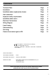
TECHNICAL DATA OVERALL DIMENSIONS CUT OUT DIMENSIONS Width: Depth: Thickness: Height: Weight: Width: Depth: 580 mm. 510 mm. 30 mm. 72 mm. 9 Kg. 560 mm. 480 mm. SUPPLY CONNECTIONS Gas: RC 1/2 inch (1/2 inch male) Rear right hand corner Electric: 240V 50Hz supply, 3 core flexible cable with non rewireable plug fitted with a 3 amp cartridge fuse. This appliance complies with the EEC Directive No 89/336, concerning suppression of radio electrical interference.
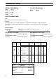
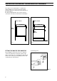
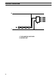
INSTALLATION IMPORTANT It is essential that a competent installer is employed to fit this appliance. The manufacturer will not accept liability, should the above instruction or any of the other safety instructions incorporated in this book be ignored. On the end of the shaft, which includes the GJ 1/2" threaded nut, adjustment is fixed so that the washer is interposed between the components as shown in Figure 1.
INSTALLATION ABOVE CUPBOARD OR DRAWER If the hob is to be installed above a cupboard or drawer it will be necessary to fit a heat resistant board below the base of the hob on the underside of the work surface.
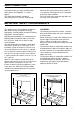
GAS CONNECTION Connection to the gas supply should be with either rigid or semi-rigid pipe, i.e. steel or copper. The connection should be suitable for connecting to RC 1/2 (1/2 BSP male thread). When the final connection has been made, it is essential that a thorough leak test is carried out on the hob and installation. Ensure that the main connection pipe does not exert any strain on the hob.
INSTALLATION ABOVE OVEN When ever the hob is fitted above an oven in a built under situation, we recommend the hob sould be fitted and connected into the hob aperture first using 8 mm., small soft copper pipe, also using recognised connector fittings. The pipework should be routed to the back od the housing unit. Before commencing it would be advisable to slide the oven into the housing and view through the hob aperture cut-out to identify the space available for pipework.
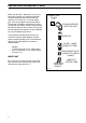
ELECTRICAL CONNECTIONS All electrical connections must be carried out by competent persons in accordance with the current regulations. This appliance is designed to be connected to a 240V 50Hz AC electrical supply. The appliance is fitted with a 3 core flexible supply cord incorporating a moulded 3amp plug top fitted with a 3amp ASTA rated fuse. THIS APPLIANCE MUST BE EARTHED. When replacing the plug top fuse only a 3amp BS1362 ASTA rated replacement should be used.
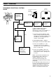
WIRING DIAGRAM N 220 240 1 2 3 0 4 2 1 L 1. TAPS IGNITOR SWITCHES 2.
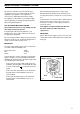
FAULT FINDING PRELIMINARY ELECTRICAL SYSTEMS CHECK Blue Green Yellow START Isolate appliance and carry out: A: Earth Continuity check. Neutral Wire Blue ( ) E( ) FUSE Earth Wire Green/Yellow Brown SOCKET (face view) PLUG (with cover removed) N L Blue Brown Green Yellow NO YES Carry out: C: Polarity check. Electricity supply should now be satisfactory. A. EARTH CONTINUITY CHECK appliance must be electrically disconnected - meter set on Ω (Ohms) x 1 scale and adjust zero if necessary.
IGNITION SYSTEM / GAS IGNITION Ignitor does not spark YES Check gas supply at burner NO Check plug top fuse and replace if necessary Light burner manually Check by pass simmer adjusted Check polarity and earth continuity of supply point Check position of the electrode Check earth continuity of appliance Check continuity from 'N' on the mains connector block and "O" on the ignitor unit Check continuity from the tip of each electrode to the terminals 1 to 4 on the ignitor unit Check continuity fro
COMMISSIONING When the hob has been fully installed it will be necessary to check the minimum flame setting. To do this, follow the procedure below. - Turn the gas tap to the MAX position and ignite. - Set the gas tap to the MIN flame position then turn the control knob from MIN to MAX several times. If the flame is unstable or is extinguished follow the procedure below. a) Minimum adjust.screw b) Tap Procedure 1: Re-ignite the burner and set to MIN.
SERVICING A: Removal Of Control Panel 1. Remove all the control knobs. 2. Using a levering action of the hand on the rear area of the panel, pull it up until it disconnects from its hooks. When doing this avoid using objects which could damage the hob and/or the control panel. B: Removal Of Hob Top Follow the procedure in "A" 1. Remove the panstands and each burner cap and crown. 2. Remove the 2 self tapping screws from each burner. 3.
Better Products. Better Value. TRICITY BENDIX, 99 OAKLEY ROAD, LUTON, BEDFORDSHIRE, LU4 9QQ. A Division od Emaco Limited - Registered in England No. 176547 - Registered Office. 101 Oakley Road, Luton LU4 9RJ. MODEL NO. PART NO.