GAS COOKER SG 205WL
CONTENTS Instructions for the User Instructions for the Installer Important Safety Information 4 Technical Features 18 Description of the appliance 5 Safety Advice - Gas connections 19 19 Using the appliance - Using the oven - Hints & Tips - Using the Grill - Using the Hob - Cooking chart 6 6 8 9 10 11 Installation - Location - Ventilation - Levelling 20 20 20 21 Gas connections 21 Maintenance and Cleaning 13 Conversion of gas 23 Something Not Working 15 Service & Spare Parts 16 Custo
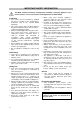
IMPORTANT SAFETY INFORMATION You MUST read these warnings carefully before installing or using the appliance. If you need assistance, contact our Customer Care Department on 08705 950950. Installation • This cooker must be installed by qualified personnel, according to the manufacturer’s instructions and to the relevant British Standards. • This cooker is heavy. Take care when moving it. Any gas installation must be carried out by a registered competent installer.
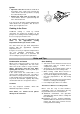
The symbol on the product or on its packaging indicates that this product may not be treated as household waste. Instead it shall be handed over to the applicable collection point for the recycling of electrical and electronic equipment. By ensuring this product is disposed of correctly, you will help prevent potential negative consequences for the environment and human health, which could otherwise be caused by inappropriate waste handling of this product.
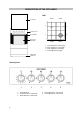
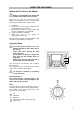
DESCRIPTION OF THE APPLIANCE Hob 2000W Cooker lid 1000W 2 3 1 4 Control panel Door handle Oven door with glass 2000W 1. 2. 3. 4. 2600W Front left burner (semi-rapid) Back left burner (semi-rapid) Back right burner (auxiliary) Front right burner (rapid) Adjustable small feet Control panel SG205WL 1. Oven/grill knob 2. Front left burner control knob 3. Back left burner control knob 6 4. Back right burner control knob 5.
USING THE APPLIANCE Before the First Use of the Cooker Remove all packaging both inside and outside of the cooker, before using it. Before first use, the oven should be heated without food. During this time, an unpleasant odour may be emitted. This is quite normal. 1. Lift the lid. 2. Remove the oven accessories and ensure all packaging has been removed. 3. Ignite the oven burner (see instructions) and turn the control knob to 9 (maximum). 4. Open a window for ventilation. 5.
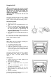
Ignition • Open the oven door and lift the small lid on the bottom of the cavity, push and turn the control knob to the left to position 9, keeping the control knob pressed. • Release the knob after 10 seconds and check that the burner is ignited through the holes in the bottom lid. If for any reason the flame should extinguish turn control knob to the off position, after at least 1 minute, try to re-ignite the oven.
Using the Grill Accessible parts may become hot when the grill is in us. Children should be kept away. The grill pan will become hot during use, always use oven gloves when removing or replacing a hot grill pan. All grilling must be carried out with the oven door closed. Heat comes from the top of the oven. It is suitable for grilling meat (steak, bacon etc…) that remains tender, for toast or to brown food already cooked. Grill burner ignition • Open the oven door.
Browning • Turn the oven/grill control knob to the “grill” position. • Place the dish on the grid and slide it on shelf guide 2 or 3. • Leave the dish under the grill for a few minutes. Using the Hob The Hob Burners The symbol on the knob corresponds to a symbol on the control panel (See description of appliance). Each burner has a safety device. In case the flame dies out the safety device stops the gas supply.
COOKING CHART Food Tray type or dimension (dxwxh) cm Material of the tray No. of tray Preheating Shelf Thermospos. tat pos. Cooking Time (min) Thermostat pos. Time (min) Roasting meal - beef Roasting tray delivered with the cooker - lamb Enamelled - pork and veal 1 2 5 15 5 20 min. for each 0.5 Kg / rare 25 min. for each 0.5 Kg/medium 30min. for each 0.5 Kg/well done 1 2 5 15 5 25 min. for each 0.5 Kg/ medium 30min. for each 0.5 Kg/well done 1 2 5 15 5 30 min. for each 0.
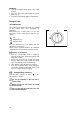
Selecting the Correct burner Above every knob there is a symbol for the corresponding burner. For good cooking results, always choose pans, which correctly fit to the diameter of the burner used (see figs). Choose thick, flat bottom pots. We recommend the flame be lowered as soon as the liquid starts boiling. For a correct ignition always keep the burner ring and the spark plugs clean. The following diameter pans can be used: Burner Rapid Semi-Rapid Auxiliary Power (kW) 2,60 2,00 1,00 Diameter (mm) min.
MAINTENANCE AND CLEANING The oven should be kept clean at all times. A build-up of fats or other foodstuffs could result in a fire, especially in the grill pan. Before cleaning, ensure all control knobs are in the OFF position, and the appliance has cooled completely. Cleaning materials Before using any cleaning materials on your oven, check that they are suitable and that the manufacturer recommends their use. DO NOT clean the oven door while the glass panels are warm.
Hob After every use wipe with a soft cloth well wrung out in warm water to which a little washing up liquid has been added, avoiding any leakage through the holes of the hob. Rinse and dry with a soft cloth. To remove more stubborn stains, wet and leave to dissolve, do not scratch and avoid the use of abrasive or caustic products that could damage the enamel. Burner cap Burner ring Burners The burner caps and crowns can be removed for cleaning.
SOMETHING NOT WORKING If the appliance is not working correctly, please carry out the following checks, before contacting your local Service Force Service Centre. IMPORTANT: If you call out an engineer to a fault listed below, or to repair a fault caused by incorrect use or installation, a charge will be made even if the appliance is under guarantee. Symptoms Solutions 1.
SERVICE AND SPARE PARTS In the event of your appliance requiring service, or if you wish to purchase spare parts, please contact your local Service Force Centre by telephoning:- 08705 929929 Your telephone call will be automatically routed to the Service Force Centre covering your postcode area. For the address of your local Service Force Centre and further information about Service Force, please visit the website at www.serviceforce.co.
GUARANTEE CONDITIONS Standard Guarantee Conditions We Tricity Bendix undertake that if, within 12 months of the date of the purchase, this Tricity Bendix appliance or any part thereof is proved to be defective by any reason only of faulty workmanship or materials, we will, at our option, repair or replace the same FREE OF ANY CHARGE for labour, materials or carriage on condition that: • The appliance has been correctly installed and used only on the electricity supply stated on the rating plate.
INSTRUCTIONS FOR THE INSTALLER TECHNICAL FEATURES Free standing Hob Class 1 Cover Pan support Front right Back right Front left Back left Oven Oven Oven power Grill Grill power Accessories Oven grid Dripping pan / roasting tray Trivet Legs Dimensions Height with the lid closed Height to the hob Width Depth Painted Enamelled Rapid Auxiliary Semi-rapid Semi-rapid This appliance complies with the following EEC Directives : 93/68 ; 73/23 (Low Voltage Directive) and subsequent modifications, 89/336, 9
ADVICE FOR SAFETY Gas connections • • • • • Before installation ensure gas type and pressure and the pre-setting of the appliance are consistent. This appliance must be installed only in a room with good ventilation. This appliance must not connect to a flu. It has to be installed and connected in accordance with the rules in force. Special attention should be paid to ventilation requirements. The adjacent furniture panels have to be heat resistant or protected by such material.
INSTALLATION Location of appliance L.P.G. cookers or ovens MUST NOT be installed below ground level, i.e. in a basement, or aboard any boat, yacht or other vessel. The cooking appliance must be fitted with a stability chain firmly secured to the wall (see fig). Ventilation The room containing the cooker should have an air supply in accordance with B.S. 5440: Part 2: Current Editions. The following requirements for ventilation must be met.
Levelling Fix the support with two legs by means of washer and nuts, delivered with the cooker, see the figure. GAS CONNECTIONS Your cooker is delivered adjusted for the kind of gas stated on the rating plate.
Connection shall be by means of an appliance flexible connector for use with a self-sealing plug-in device, complying with: Flexible hoses, end fittings and sockets for gas burning appliances – BS 669; LPG flexible connections must be of a type suitable for LPG and capable of operation up to 50mbar and to carry a red strips, band or label.
CONVERSION OF GAS Your cooker is designed to work with propane or butane, and is convertible for use with natural gas. The natural gas conversion kit is available from your Service Force Centre and must be fitted by a Registered engineer/ competent person.
Replace the nozzles of the hob burners Every appliance has spare nozzles for every type of gas. The whole length of every nozzle is marked in millimetres on the nozzle. Hob burners • • • Remove the pan support; Remove the caps and the burner crowns; Using a No 7 socket spanner unscrew the nozzles and replace them with those required for the type of gas in use (see table no.1). Reassemble the parts following the same procedure in reverse. These burners do not need any primary air regulation.
Replace the nozzles of the oven burners Oven burner To replace the gas oven nozzle, follow this procedure: • Check the table no.1 for diameter of nozzle; • Remove the oven removable base panel; • Remove the screw "B" on the oven burner; • Remove the oven burner by pushing it backwards. • Replace the nozzle (C) by means of a No 10 socket spanner; Reassemble the parts following the same procedure in reverse.
Adjustment of minimum level Oven burner • • • • • Remove the top pan support as well as the burner caps and the burner crowns. Unscrew and remove the 2 top plate-fixing screws and remove the top plate. Light the burner knob on position 9 and leave the oven door closed for about 10 min. Turn the knob slowly to position 1. Pull off the knob to adjust minimum flow. • Unscrew or screw the by-pass screw (is it above of tap shaft) until a regular small flame is reached.
Customer Care Department Electrolux Major Appliances Addington Way LutonBedfordshire, LU4 9QQ Tel: 08705 727 727 (*) SG205WL - 342 725 716 -B-16012007 © Electrolux plc 2005 From the Electrolux Group. The world’s No.1 choice The Electrolux Group is the world’s largest producer of powered appliances for kitchen, cleaning and outdoor use.