GAS COOKER SG 210COOKER ELECTRIC SIE 233 GB
CONTENTS Instructions for the User Instructions for the Installer Important Safety Information 4 Technical Features 17 Description of the appliance 5 Safety Advice - Gas connections 18 18 Using the appliance - Using the oven - Hints & Tips - Using the Grill - Using the Hob 6 6 8 10 11 Electrical connections 19 Maintenance and Cleaning 12 Installation - Location - Ventilation - Levelling 20 20 20 21 Something Not Working 14 Gas connections 21 Service & Spare Parts 15 Conversion of gas
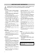
IMPORTANT SAFETY INFORMATION You MUST read these warnings carefully before installing or using the appliance. If you need assistance, contact our Customer Care Department on 08705 950950. Installation • This cooker must be installed by qualified personnel, according to the manufacturer’s instructions and to the relevant British Standards. • This cooker is heavy. Take care when moving it. Any gas installation must be carried out by a registered competent installer.
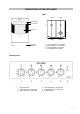
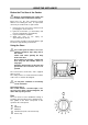
DESCRIPTION OF THE APPLIANCE Hob 2000W 1000W Control panel Door handle 2 3 1 4 Oven door 2000W Adjustable small feet 1. 2. 3. 4. 2600W Front left burner (semi-rapid) Back left burner (semi-rapid) Back right burner (auxiliary) Front right burner (rapid) Control panel 1. Oven/grill knob 2. Front left burner control knob 3. Back left burner control knob 4. Back right burner control knob 5. Front right burner control knob 6.
USING THE APPLIANCE Before the First Use of the Cooker Remove all packaging both inside and outside of the cooker, before using it. Before first use, the oven should be heated without food. During this time, an unpleasant odour may be emitted. This is quite normal. 1. Remove the oven accessories and ensure all packaging has been removed. 2. Ignite the oven burner (see instructions) and turn the control knob to 9 (maximum). 3. Open a window for ventilation 4.
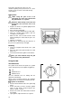
Ignition Attention: when turning on the oven and grill burner the oven door has to be opened. • • • Open the oven door and lift the small lid on the bottom of the cavity, push and turn the control knob to the left to position 9, keeping the control knob pressed. At the same time, push the electronic ignition knob (see fig). Keep it pushed until the gas ignites (1 spark / second). Release the knob after 10 seconds and check that the burner is ignited through the holes in the burner cover.
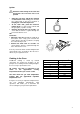
Hints and Tips Condensation and steam Oven Cooking When food is heated it produces steam in the same way as a boiling kettle. The oven vents allow some of this steam to escape. However, always stand back from the oven when opening the oven door to allow any build up of steam or heat to release. If the steam comes into contact with a cool surface on the outside of the oven, e.g. a trim, it will condense and produce water droplets. This is quite normal and is not a fault with the oven.
Using the Grill When using the grill it has to be supervised, the oven door opened and the grill deflector “A” in place. A Heat comes from the top of the oven. It is suitable for grilling meat (steak, bacon etc…) that remains tender, for toast or to brown food already cooked. Grill burner ignition Attention: when turning on the oven and grill burner the oven door has to be opened.
Heat comes from the top of the oven. It is suitable for grilling meat (steak, bacon etc…) that remains tender, for toast or to brown already cooked dishes. Grilling meat When using the grill it has to be supervised, the oven door opened and the grill deflector “A” in place. Attention: when turning on the oven and grill burner the oven door has to be opened. • Prepare the meat to be grilled, lightly brush it with oil on both sides. • Place it on the roasting grid.
OR Power Cut • Push the corresponding knob in completely and turn it left to the symbol “large flame” symbol and ignite with a match. • Release the knob and watch that the burner has ignited. Upon ignition, adjust the flame as required. • If for any reason the flame should extinguish turn off the relevant control knob, leave for at least one minute and then re-ignite. Extinguishing of burners Turn the knob clockwise to mark « ». Do not put anything on the hob that is liable to melt.
MAINTENANCE AND CLEANING The oven should be kept clean at all times. A build-up of fats or other foodstuffs could result in a fire, especially in the grill pan. Before cleaning, ensure all control knobs are in the OFF position, and the appliance has cooled completely. Before any maintenance or cleaning can be carried out, you must DISCONNECT the cooker from the electricity supply.
DO NOT clean the oven door while the glass panels are warm. If this precaution is not observed the glass panel may shatter. If the door glass panel becomes chipped or has deep scratches, the glass will be weakened and must be replaced to prevent the possibility of the panel shattering. Contact your local Service Centre who will be pleased to advise further. IMPORTANT: The inner door glass must be in place when using the oven.
SOMETHING NOT WORKING If the appliance is not working correctly, please carry out the following checks, before contacting your local Service Force Service Centre. IMPORTANT: If you call out an engineer to a fault listed below, or to repair a fault caused by incorrect use or installation, a charge will be made even if the appliance is under guarantee. Symptoms Solutions 1.
SERVICE AND SPARE PARTS In the event of your appliance requiring service, or if you wish to purchase spare parts, please contact your local Service Force Centre by telephoning:- 08705 929929 Your telephone call will be automatically routed to the Service Force Centre covering your post code area. For the address of your local Service Force Centre and further information about Service Force, please visit the website at www.serviceforce.co.
GUARANTEE CONDITIONS Standard Guarantee Conditions We Tricity Bendix undertake that if, within 12 months of the date of the purchase, this Tricity Bendix appliance or any part thereof is proved to be defective by any reason only of faulty workmanship or materials, we will, at our option, repair or replace the same FREE OF ANY CHARGE for labour, materials or carriage on condition that: • The appliance has been correctly installed and used only on the electricity supply stated on the rating plate.
INSTRUCTIONS FOR THE INSTALLER TECHNICAL FEATURES Free standing Hob Class 1 Pan support Front right Back right Front left Back left Hob ignition Oven Oven Oven power Grill Grill power Oven ignition Accessories Trivet Dripping pan / roasting tray Roasting grid Grill deflector Legs Dimensions Height to the hob Width Depth Enamelled Rapid Auxiliary Semi-rapid Semi-rapid 2,60 kW 1,00 kW 2,00 kW 2,00 kW Spark Gas 3,20 kW Gas 2,50 kW Spark Chromed Enamelled Chromed Enamelled 880- 890 mm 500 mm 600 mm
ADVICE FOR SAFETY Gas connections • • • • • Before installation ensure gas type and pressure and the pre-setting of the appliance are consistent. This appliance must be installed only in a room with good ventilation. This appliance must not connect to a flu. It has to be installed and connected in accordance with the rules in force. Special attention should be paid to ventilation requirements. The adjacent furniture panels have to be heat resistant or protected by such material.
ELECTRICAL CONNECTIONS Any electrical work required to install this cooker should be carried out by a qualified electrician or competent person, in accordance with the current regulations. A cut off plug inserted into a 13-amp socket is a serious safety (shock) hazard. Ensure that the cut off plug is disposed of safety. THIS COOKER MUST BE EARTHED. The manufacturer declines any liability should these safety measures not be observed.
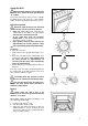
INSTALLATION Location of appliance L.P.G. cookers or ovens MUST NOT be installed below ground level, i.e. in a basement, or aboard any boat, yacht or other vessel. The cooking appliance must be fitted with a stability chain firmly secured to the wall (see fig). Ventilation The room containing the cooker should have an air supply in accordance with B.S. 5440: Part 2: Current Editions. The following requirements for ventilation must be met.
Levelling Fix the support with two legs with the washer and nuts, delivered with the cooker, see the figure. • Unscrew the legs as far as possible (approx. 16mm from fully screwed in). • Place the plinth (pos.3) so that the springs (pos.2) reach the threaded area of the legs and the clamp of the plinth (pos.4) is in front of the holes (pos.5) on the under side of the structure.
Fixing and use of the 2 clips provided with the cooker The enclosed gas hose fixing clips must be fixed to the back of the cooker, dependant on the position of the supply bayonet connector (see fig.). clip When selecting the most suitable position for the clips, please ensure that the gas hose cannot come into contact with any part of the “Hot zone” (indicated by the shaded areas on the illustration) when pushing the cooker into its final position.
CONVERSION OF GAS Your cooker is designed to work with natural gas, and is convertible for use with propane or butane. The LPG conversion kit is available from your Service Force Centre and must be fitted by a Registered engineer/ competent person.
Replace the nozzles of the hob burners Every appliance has spare nozzles for every type of gas. The whole length of every nozzle is marked in millimetres on the nozzle. Before any modifications or conversion to a different kind of gas, you must DISCONNECT the cooker from the electricity supply and ensure that all control knobs are in the OFF position, and the appliance has cooled completely.
Replace the nozzles of the oven burners Oven burner To replace the gas oven nozzle, follow this procedure: • Check the table no.1 for diameter of nozzle; • Remove the oven removable base panel; • Remove the screw on the oven burner rod at the rear of the oven; • Remove the oven burner by pushing it backwards. • Replace the nozzle "C" by means of a No 10 socket spanner; Reassemble the parts following the same procedure in reverse.
Adjustment of minimum level Oven burner • • • • • • • Remove the top pan support as well as the burner caps and the burner crowns. Unscrew and remove the 2 top plate-fixing screws and remove the top plate. Light the burner knob in the maximum position and leave the oven door closed for about 10 mins. Turn the knob slowly to the minimum position. Pull off the knob to adjust minimum flow. Unscrew or screw the by-pass screw until a regular small flame is reached.
Customer Care Department Tricity Bendix 55-77 High Street Slough Berkshire SL1 1DZ Tel: 08705 950 950 SG 210 - 342724765 © Electrolux plc 2003 From the Electrolux Group. The world’s No.1 choice The Electrolux Group is the world’s largest producer of powered appliances for kitchen, cleaning and outdoor use. More than 55 million Electrolux Group products (such as refrigerators, washing machines, vacuum cleaners, chain saws and lawn mowers) are sold each year to a value of approx.