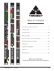
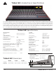
Trident 68 Introduction & Specifications The Series 68 analog consoles have been developed to deliver the core feature set most often needed for analog recording. The 68’s are Split/lnline consoles with individual channels in 8-way panels. Using an 8 subgroup configuration and incorporating 6 Aux sends, its routing options are vast and simple to use. Connections are fast and easy with DB-25’s throughout the board and XLR’s for Master and Main outputs.
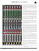
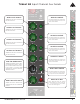
Trident 68 The Input Module
Trident 68 Input Channel Mic/Line Options +48V
Channel Aux Sends Trident 68 Input AUX 2 Level Control Adjusts the mix level of Channel into the Aux 2 bus.
This switch inserts the 3-band EQ and High Pass Filter into the channel/monitor (see EQ TO MON switch description below) signal path.
EQ to MON Assigns the 3 band channel EQ to the Monitor Section, removing it from the channel path.
Trident 68 Input Channel Group Assignment Channel Signal Indicators Assigns the Channel post-fader signal to Group 5 and 6 mix buses through the Channel Pan Control.
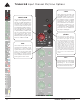
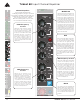
Trident 68 Group Module Section The Group section of the console greatly enhances the flexibility of the TRIDENT 68 console and provides a number of different functions. There are 8 Group channels provided on the Group Module section of the console, these are mounted on a single panel and each Group strip controlling the associated group mix bus outputs. The groups can be used as audio subgroups for combining and processing a collection of input channels.
Trident 68 Group Metering Section 12-Segment Bargraph Meter
Trident 68 Group EFX Section RETURN EFX RTN BAL Control EFX RTN MUTE
Trident 68 Group Monitor Aux Sends AUX 5-6 Level Control Adjusts the mix level of the Monitor Input into the Aux 5 and Aux 6 buses.
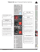
Trident 68 The Master Module Monitor Section The Master section of the TRIDENT 68 console contains all of the controls that affect the overall functionality of the console. An accurately matched 100mm stereo fader controls the level of the master stereo balanced outputs. A talkback system is provided which incorporates an internal high quality electret microphone. The talkback signal can be routed to the auxiliary buses and the 8 subgroups.
Trident 68 Master Monitor Section LEVEL SOLO ACTIVE STEREO IN JACK (3.5mm, 1/8”) This jack allows the engineer to plug in an external stereo signal via a standard 1/8” wire cable ( i.e iPod) which can then be selected to the main Control Room Monitors. To assign this signal into the main monitors, the user has to depress the 2-TRK 1 switch.
Trident 68 MasterSUM Talkback Section MONO DIM HEADPHONE HEADPHONE JACK (3.5mm, 1/8”) LEFT/RIGHT INSERT ON SOLO MASTER To monitor the console on headphones the engineer can plug them into this jack. The headphones jack is driven by a dedicated high quality, high current stereo amplifier. LEVEL SOLO ACTIVE MONITOR INPUTS STEREO IN TALKBACK LEVEL CONTROL Directly behind this location is situated the internal high quality electrets microphone.
Trident 68 Rear Connections | Power Supply Input Connector Master Connector C M Y CM MY CY CMY K C M Y CM MY CY CMY K Power Supply 19 Composite Trident 68 Owners Manual
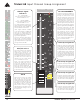
DSub-25 Pinout — 13 26 27 G 25 23 22 10 9 8 21 20 19 7 18 6 5 17 16 4 2 3 CH1 IN/OUT - CH1 IN/OUT + CH2 IN/OUT - CH2 IN/OUT + CH3 IN/OUT - CH3 IN/OUT + CH4 IN/OUT - CH4 IN/OUT + CH5 IN/OUT - CH5 IN/OUT + CH6 IN/OUT - CH6 IN/OUT + CH7 IN/OUT - CH7 IN/OUT + 13 CH8 IN/OUT - — G + G 25 G 1 25 CH8 IN/OUT + + 2 26 27 — G G 1 25 + 2 24 — + — G 3 23 17 G 4 22 + + — G 5 21 6 20 — G + — G 19 7 18 + 15 14 + Position 13 12 11 10 9
Trident 68 Warranty Information Tident Audio Developments Limited Warranty Statement The following outlines the warranty periods for The Trident 68 Analogue console. All extended coverage is based on the timely registration of said products within the 30 days of purchase to the original purchaser from the date of Proof Of Purchase. Proof of purchase is the original Bill Of Sale or Sales Invoice from an authorized dealer. Inquire about extended warranty.
Trident 68 Input Module Flow Diagram
Trident 68 Group Module Flow Diagram
Trident 68 Master Module Flow Diagram
Trident 68 Warning & Policies C AU T IO N RISK OF ELECTRIC SHOCK DO NOT OPEN ! CAUTION: TO REDUCE THE RISK OF ELECTRICAL SHOCK, DO NOT REMOVE COVER. NO-USER SERVICEABLE. The lightning flash with arrowhead symbol, within equilateral triangle, is intended to alert the user to the presence of uninsulated “dangerous voltage” within the product’s enclosure that may be of sufficient magnitude to constitute a risk of electric shock to persons.
Trident 68 Input Channel Recall Sheet Project: _____________________ _____________________________________________________________ _____________________________________________________________ _____________________________________________________________
Trident 68 Group Channel Recall Sheet Date: _____________________ Engineer: _____________________ Artist: _____________________ Project: _____________________ Session Notes _____________________________________________________________ ______________
Trident 68 Master Channel Recall Sheet Date: _____________________ Engineer: _____________________ Artist: _____________________ Project: _____________________ Session Notes _____________________________________________________________ LEFT/RIGHT INSERT ON _____________________________________________________________ _____________________________________________________________ _____________________________________________________________ SOLO MASTER LEVEL SOLO ACTIVE MONITOR