
User's Manual


15
Assign New Access Codes
With a valid authority code (see page 3 or 11), an access code can be
programmed with the following instructions.
1. Press the (5/6) button for 5 seconds, the keypad will beep. The
backlighting LED of the keypad will flash indicating the learn
mode.
2. Enter in the 5-digit authority code (see page 3 or 11). Keypad will
provide a long beep that will stop after you have defined an
access number.
3. Press and release the button that corresponds to the access
number. For example, press (1/2) button for access #1 and press
(3/4) button for access #2. During this activity you are defining 1
of 5 access numbers. A subsequent code will be assigned to this
access #. The keypad will provide a confirmation beep after this
single button press.
4. Enter in your new 5-digit access code. The keypad will provide
confirmation beeps.
5. Re-enter new access code. The keypad will provide confirmation
beeps.
Repeat process to assign additional access codes.
Up to 5 different access codes can be assigned at one time. As
additional access codes are defined, pre-existing access codes are
overwritten. For example, if a new access code is assigned for access
#3, the previous access #3 code is no longer valid.
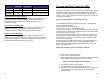
The following area can be used to document the access code
assignments.
Access
#
User Name
Digit
1
Digit
2
Digit
3
Digit
4
Digit
5
1
2
3
4
5
16
Troubleshooting
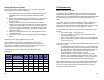
CAN Error Diagnostic Codes:
The following defines diagnostic code for door module and keypads.
Similar codes are used with both types of modules, door module and
keypad module. The keypad module using back lighting LED and buzzer
for communicating codes while the door module uses D16 and D17
LEDs.
1) At power up the door module will attempt to claim its address on the
CAN bus. This takes 1/4 second. Afterwards, it waits another 1/4
second then sends out a request to all the other nodes on the bus to see
who's out there. After this, it turns on both LEDs for 1 second.
This “long blink" of the LEDs is intended to tell you that the CPU reset
and why:
One 1 second blink = normal power on
Two 1 second blinks = watchdog timer reset the CPU (this
indicates a software bug)
Three 1 second blinks = brownout reset. The power supply fell
below the minimum requirement for a moment. This threshold is
set for 2.0 V for now.
2) After the long blinks, a series of "short blinks" indicate other errors that
may have occurred:
Two short blinks = the CAN bus is inactive. This means there is
an electrical problem with the CAN bus (possibly a problem with
bus termination), or simply that the I/O module is the only node
attached to the bus. The I/O module will continue running
assuming that it is the only node in the vehicle.
Three short blinks = the I/O module couldn't claim its CAN
address. This is probably because another I/O module on the
bus is set to the same function instance. This is considered a
fatal error so the I/O module will reset itself and try again.
NOTE: CAN communications errors and address claim problems take a
while to detect because of the retry code in the I/O module, so if any
errors are found the initial power-on long blink will not occur until a
couple of seconds after power on.