INTEGRATOR'S GUIDE Trimble TDL 450i ®
AMERICAS & ASIA-PACIFIC Trimble Navigation Ltd. Integrated Technologies 510 DeGuigne Drive Sunnyvale, CA 94085 USA +1-408-481-8070 Phone +1-408-481-8984 Fax EUROPE & MIDDLE EAST Trimble Navigation Ltd. Integrated Technologies HAL Trade Center Bevelandseweg 150 1703 AX Heerhugowaard Netherlands +31-725-724-408 Phone +31-725-348-288 Fax RUSSIA Trimble Navigation Ltd. Integrated Technologies Tel: +7 495 5041081 Email: rusales-pc@trimble.com CHINA Trimble Navigation Ltd.
Contact Information Communications Commission rules. Trimble Navigation Limited Canada Integrated Technologies 510 DeGuigne Drive Sunnyvale, CA 94085 USA This digital apparatus does not exceed the Class B limits for radio noise emissions from digital apparatus as set out in the radio interference regulations of the Canadian Department of Communications.
Safety Information Before you use your radio, ensure that you have read and understood this publication, as well as safety requirements. CAUTION – A license is required before operating radio communication equipment. Warnings and cautions An absence of specific alerts does not mean that there are no safety risks involved. Always follow the instructions that accompany a Warning or Caution. The information they provide is intended to minimize the risk of personal injury and/or damage to the equipment.
– 15 cm (approximately 6 in) for the TDL 450i radio @ 1 W • Do not operate the transceiver unless all RF connectors are secure and any open connectors are properly terminated. • Avoid contact with the antenna while operating the transceiver. • Do not operate the transceiver with a damaged antenna. If a damaged antenna comes in contact with the skin, a minor burn may result. • Do not operate the equipment near electrical blasting caps or in an explosive atmosphere.
installations, you should not use frequencies set aside for itinerant operations, but should coordinate a frequency based on the fixed area operation. Regulations differ from country to country, please be aware of the local regulations before using radio equipment. Automatic station identification For operation in the United States, the FCC requires that radio transmitters broadcast a station identifier every 15 minutes. The station identifier is the call sign assigned to you on the station license.
Contents Safety Information . . . . . . . . . . . . . . . . . . . . . . . . . . . . . . . . . . . . . . . . . . . . . . . . . . . . . . 4 Introduction . . . . . . . . . . . . . . . . . . . . . . . . . . . . . . . . . . . . . . . . . . . . . . . . . . . . . . . . . . . 8 Getting Started . . . . . . . . . . . . . . . . . . . . . . . . . . . . . . . . . . . . . . . . . . . . . . . . . . . . . . . . . 8 Interface Port Pin Out . . . . . . . . . . . . . . . . . . . . . . . . . . . . . . . . . . . . . . . . . . .
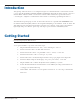
Introduction This guide provides information concerning the integration of the TDL 450i radio modem transceiver into your product (Model Numbers XDLM-0, XDLM-1 and XDLM-2). This guide should be used in conjunction with the XDLCONF User’s Guide – Dealer Version that should be referenced for general information concerning the configuration of TDL 450i modems, and also for detailed programming information.
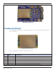
TDL 450i in Test Board Interface Port Pin Out The standard TDL 450i transceiver comprises a 30-pin port for power, data and interfacing with other electronic devices. 30 Pin TDL 450i Board The following signals are available on the 30-pin connector: Pin 1 2 3 4 5 6 Name GND DO NOT USE TX DO NOT USE GND DO NOT USE TDL 450i Intergrator’s Guide Description GROUND FOR SIGNAL AND POWER FACTORY USE ONLY, NO CONNECTION TX DATA, DTE SERIAL PORT, 3V CMOS (3.
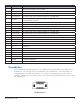
Pin Name Description 7 GND GROUND FOR SIGNAL AND POWER 8 9 10 DO NOT USE GND DO NOT USE 11 CONFIG 12 13 14 15 16 17 18 19 20 21 22 23 24 25 26 27 28 29 30 DO NOT USE DO NOT USE RX DO NOT USE DO NOT USE DO NOT USE VCC GND GND GND GND VCC VCC VCC VCC VCC VCC POWER GND FACTORY USE ONLY, PLEASE LEAVE NO CONNECTION GROUND FOR SIGNAL AND POWER FACTORY USE ONLY, PLEASE LEAVE NO CONNECTION I/O TO FORCE RADIO SWITCH BETWEEN OPERATING MODE AND CONFIGURATION MODE FACTORY USE ONLY, PLEASE LEAVE NO CONNECTIO
Antenna Port A coaxial antenna port is provided for connecting the antenna system to the TDL 450i transceiver. The antenna connector is a 50-Ohm MMCX type. Appendix B provides part numbers and manufacturer information for compatible interface and RF connectors. Pacific Crest also provides custom manufactured cables designed to your specific needs. Contact us for a quotation for your specific cabling requirements. Warning: Don’t transmit without first connecting an antenna.
Parameter Default Link Rate 9600 bps GMSK EOT 50 ms Repeater Delay 0 CSMA On* FEC On Scrambling On Sensitivity High Local Address 0 Destination Address 255 *CSMA is required to be on only inside the United States. You should turn CSMA off in EU countries. TDL 450i Factory Default Settings Up to 32 frequencies are stored in the configuration memory called the channel table.
Electrical Considerations Power Supply The TDL 450i transceiver has a power supply connection on Pin 18 and Pins 23 to 28 of the interface connector. Pins 1, 5,7, 9,30 and Pins 19 to 22 are connections to both power ground and serial interface signal grounds. Note that these pins are tied to a common point on the TDL 450i transceiver.
Error Codes The TDL 450i transceiver performs a variety of power-up and run-time tests to assure optimal operation. Tests include environmental as well as electrical measurements designed to avoid damage to the unit while maintaining adequate operation. A 50Ω impedance coaxial MMCX style RF connector is provided for attachment to an external antenna system. The MMCX connector offers a positive friction locking mechanism that is very reliable.
Circuit Center Frequency (MHz) Bandwidth (MHz) First IF 54.45 0.015 Second IF 0.450 0.010 TDL 450i Frequency Plan Mechanical Considerations EMI interferers The TDL 450i transceiver is easily mounted inside new and existing products. The TDL 450i transceiver is specifically designed for operation in harsh environments. For best performance, mount the radio away from potential EMI radiators and route RF signals apart from digital signals.
approximately 6 Watts of heat at full RF power out. Refer to Appendix A for mounting diagrams and specification. Materials The TDL 450i transceiver is housed in a metal shield that is a conductor and is electrically connected to the ground and signal ground pins. Service and Support Philosophy Pacific Crest is dedicated to providing the very best service and support possible. We recognize that the success of our business is directly related to the success our customers have in using our products.
Pacific Crest warrants its TDL 450i transceiver radio modem products against defects in materials and workmanship for a period of one year from receipt by the end user. During the warranty period, Pacific Crest will, at its option, either repair or replace products that prove to be defective. Exclusions Should Pacific Crest be unable to repair or replace the product within a reasonable amount of time, a refund of purchase price may be given upon return of the product.
TEST FIXTURE TOOLING HOLE DO NOT USE FOR MOUNTING [44.65] 1.758 TEST FIXTURE TOOLING HOLE DO NOT USE FOR MOUNTING [3.18] 4x 0.125 [3.56] .140 [69.85] 2.750 [23.37] .920 [39.50] 1.555 [46.61] 1.835 KEEPOUT AREA BOTH SIDES COMPONENTS AND TEST POINTS LOCATED HERE .100 INCH MINIMUM CLEARANCE [9.91] .390 [15.57] .613 [1.27] .050 [21.34] .840 [54.66] 21.52 [8.74] .344 [2.39] .094 [1.63] .064 [8.05] .
RF CONNECTOR RIGHT SIDE MMCX FARSIDE DATA CONNECTOR AVX TDL 450i Mounting Template with Shields Appendix B - Cables and Connectors Value-Added Cable Products Pacific Crest manufactures a wide variety of high-quality custom cables in support of its OEM customers. Contact your Pacific Crest sales representative to discuss your custom cable requirements. Interface Connector The 30-pin data/power header is a Samtec TFM series housing a standard-configuration connector, AVX part number 14-5046-030-630-829.
The RF connector is compatible with an MMCX-style coaxial plug. Plugs are available from many sources and in many configurations. We use plugs manufactured by Radiall. Radiall MMCX right-angle plug for use with RG-178 cable is part number R110 172 100. Radiall MMCX straight plug for use with RG-178 cable is part number R110 083 120. Appendix C - Technical Specifications General DTE - DCE interface CMOS, 115.
Appendix D – API Commands A description of the TDL 450i transceiver Application Programmer Interface is available to qualified Pacific Crest development partners. Please contact sales@PacificCrest.com.