XDL Micro Integrator’s Guide 1 XDL Micro Intergrator’s Guide
Contact Information particular purpose. Customer support and sales contacts Notices Class B Statement – Notice to Users. This equipment has been tested and found to comply with the limits for a Class B digital device, pursuant to Part 15 of the FCC rules. These limits are designed to provide reasonable protection against harmful interference in a residential installation.
Safety Information Before you use your radio, ensure that you have read and understood this publication, as well as safety requirements. CAUTION – A license is required before operating radio communication equipment. Warnings and cautions An absence of specific alerts does not mean that there are no safety risks involved. Always follow the instructions that accompany a Warning or Caution. The information they provide is intended to minimize the risk of personal injury and/or damage to the equipment.
To assure optimal radio performance and to ensure that exposure to RF energy is within the guidelines in the above standards, observe the following operating procedures: • Do not operate a transceiver when someone is within the distance noted below of the antenna (unity gain).
Contents Safety Information . . . . . . . . . . . . . . . . . . . . . . . . . . . . . . . . . . . . . . . . . . . . . . . . . . . . . . 3 Introduction . . . . . . . . . . . . . . . . . . . . . . . . . . . . . . . . . . . . . . . . . . . . . . . . . . . . . . . . . . . 6 Getting Started . . . . . . . . . . . . . . . . . . . . . . . . . . . . . . . . . . . . . . . . . . . . . . . . . . . . . . . . . 7 Interface Port Pin Out . . . . . . . . . . . . . . . . . . . . . . . . . . . . . . . . . . . . . . . . . . .
Introduction This manual describes how to integrate the XDL Micro UHF transceiver (model numbers XDLM-0, XDLM-1 and XDLM-2) into your product. Pacific Crest recommends that you also read the XDLCONF User’s Guide for general information about configuring XDL Micro modems, and for detailed programming information. The XDL Micro is a general-purpose transceiver. It is compatible with the Pacific Crest ADL, PDL and RFM product families of radio modems.
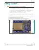
Getting Started CAUTION – You must handle the XDL Micro transceiver with care during installation. Remove the transceiver from its protective bag only in an ESD safe area. To set up the hardware components: 1. Plug the transceiver into the 30-pin connector of an I/O-test board. 2. Attach an antenna to the transceiver using an XDL radio module pigtail data cable. 3. Attach a modem cable to a 9-pin RS232 connector on the I/O-test board. 4. Attach the modem cable to a serial port on the computer. 5.
Interface Port Pin Out The standard XDL Micro transceiver comprises a 30-pin port for power, data, and interfacing with other electronic devices. The following signals are available on the 30-pin connector: 8 Pin number Function Description 1 GND Ground for signal and power 2 NC No Connection, Factory use only 3 TX Data Receives data from external device, 3 V CMOS (3.
Transmit and receive pins The XDL Micro module uses pin 3 to receive data from an external device, such as a computer, GPS receiver, or weather sensor, and uses pin 14 to transmit data to the external device. The external device transmits data to the XDL Micro transceiver on pin 3, so according to the DTE naming convention, pin 3 is called the Tx Data pin. The external device receives data from pin 14 on the XDL Micro transceiver, so this is called the Rx Data pin.
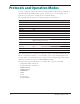
Protocols and Operation Modes You can completely configure the transceiver using the XDLCONF software. Configuration parameters define the DTE interface and the over-the-air protocol. Depending on your application, you may need to change the factory default settings. The following table shows the factory default settings of the transceiver. Setting Default setting Channel 1 Baud Rate 38400 Parity None Soft Break Disable Off TX Power 0.
Electrical Considerations Power supply The transceiver has a power supply connection on pins 18, 23, 24, 25, 26, 27, and 28 of the interface connector. If there is a potential for a ground path current loop due to incorrect power application, Pacific Crest recommends that you insert a fusible link in the signal ground to protect the transceiver. The XDL Micro transceiver is designed to operate with an unregulated DC voltage level at 3.6 ±0.4 V. The power supply must be capable of sourcing 2 A.
Power down pin Pin 29 is the active low pin used to turn off power to the XDL Micro transceiver. The VIH (Voltage Input High) minimum is 1.2 V and VIL (Voltage Input Low) maximum is 0.3 V. It has a 10 K pull-up resistor to VCC. You can leave it unconnected (NC) if you do not want to turn off the XDL Micro transceiver. Error codes The transceiver performs a variety of start-up and run-time tests to ensure optimal operation.
Frequency planning The transceiver contains a very sensitive, dual-conversion, super-heterodyne receiver. CAUTION – Radiated and conducted signals to and from the transceiver may cause problems due to interference. Correct attention to frequency planning may reduce interference from radiated or conducted frequencies that fall within the pass-bands of the filters at the IF frequencies.
Mechanical Considerations EMI interferers The transceiver is easily mounted in new and existing products. The transceiver is specifically designed for operation in harsh environments. For best performance, mount the radio away from potential EMI radiators and route RF signals apart from digital signals. CAUTION – To avoid interference between the signals, Pacific Crest recommends you do not bundle the antenna interface cable with other signal cables internal to your product.
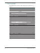
Appendix A: Mounting Guide Standard enclosure The following figure shows mounting holes locations and overall dimensions for the transceiver. CAUTION – Screws used to mount the transceiver to a mounting plate must not penetrate the mounting surface of the transceiver by more than 0.20 inches. Screws that penetrate beyond this distance may cause damage. ❶ ❷ ❸ ❶ Test fixture tooling hole. Do not use for mounting. ❷ Test fixture tooling hole. Do not use for mounting. ❸ Keepout area both sides.
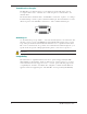
❶ ❷ 16 ❶ RF connector. Right angle MMCX. Farside. ❷ Data connector. AVX (Kyocera ELCO).
Appendix B: Cables and Connectors Value-added cable products Pacific Crest manufactures a wide variety of high-quality custom cables to support its OEM customers. To discuss your custom cable requirements, contact your Pacific Crest sales representative. Interface connector The 30-pin data/power header is an AVX Series 5046 fine-pitch connector, AVX part number AVX 24-5046-030-630-829.
Appendix C: Technical Specifications General DTE - DCE interface CMOS, 115.2 kbps maximum Power requirements External 3.6 VDC ± 0.05mV During Rx 0.45 W nominal @ 3.6 VDC During Tx 6.5 W nominal @ 3.6 VDC, 2 W RF output Radio Frequency band 403-473 MHz Frequency control Synthesized 12.5 kHz tuning resolution Frequency stability +/- 1PPM Channel spacing Channel spacing 12.5/25 kHz (user-selectable) RF transmitter output 0.5, 1.
Appendix D: API Commands A description of the XDL Micro transceiver Application Programmer Interface is available to qualified Pacific Crest development partners. Please contact sales@ PacificCrest.com.