
GPS Receiver User Manual


10 COPERNICUS REFERENCE BOARD
96 Copernicus GPS Receiver
Introduction
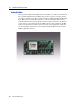
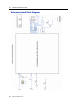
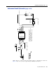
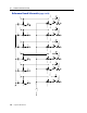
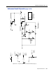
The Copernicus surface-mount GPS receiver is installed on a carrier board defined as
the Copernicus Reference Board. This board can also be used as a design reference,
providing a visual layout of the Copernicus module on a PCB including the RF signal
trace, RF connector, and the I/O connections of the 28 signal pins. The reference
board demonstrates how an 8-pin header connector can be connected to the I/O and
power sections of Copernicus, and how an RF connector can be attached to the RF
section. An antenna open and short detection and protection application circuit has
also been included on the reference board. The Copernicus GPS reference board is
RoHS compliant (lead-free).
Figure 10.1 Copernicus Reference Board, Frontside
IMAGE TO COME