
GPS Receiver User Manual


Copernicus GPS Receiver 75
RF LAYOUT CONSIDERATIONS 6
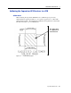
Stripline Transmission Lines
.
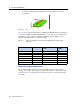
Figure 6.3 Stripline Transmission Lines
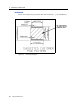
Ground plane design in stripline topology
• The stripline topology requires three PCB layers: two for ground planes and
one for signal. One of the ground plane layers may be the layer to which the
Copernicus GPS module is mounted. If this is the case,
• The top layer must be flooded with ground plane and connected to all ground
castellations on the Copernicus GPS module.
• The RF input should be connected to the signal layer below using a via.
• The layer below the signal layer is the second ground plane.
• Connect the two ground planes with vias typically adjacent to the signal trace.
• Other signals of the Copernicus GPS module may be routed to additional layer
using vias.
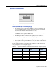
For the symmetric stripline topology where the signal trace is equal distance from
each ground plane, the following table applies:.
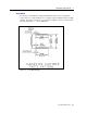
Table 6.2 Typical track widths for an FR4 material PCB substrate in Stripline topology
Substrate Material Permittivity Substrate Thickness
H (mm)
Track Width
W (MM)
1.6 0.631
1.2 0.438
1.0 0.372
FR4 4.6 0.8 0.286
0.6 0.2
0.4 0.111
0.2 N/A