
GPS Receiver User Manual

Copernicus GPS Receiver 67
APPLICATION CIRCUITS 5
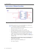
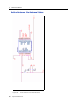
Following is a description of this schematic without antenna detection or a separate
power source for Standby Mode:
• An active Antenna is used.
• The Pin LNA_XEN is not connected.
• There is no HW reset ability through the pin XRESET, since XRESET pin is
tied High to VCC.
• HW initiated Standby Mode through the Pin XSTANDBY is possible, since
XSTANDBY pin is not tied High to VCC. Serial Command to Standby Mode
can still apply as the second method to force the module to Standby Mode.
• There is no separate power for STANDBY power.
• Both serial ports are utilized.
• Antenna open and short detection or protection is not provided. If pins 7 and 8
are left floating, they will cause the unit to report an antenna open condition
(see Table 3.2).