
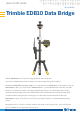
Quick Start Guide


LED 1 - EMPOWER module
This LED indicates the interaction between the EMPOWER module
and an external device.
LED 1 EMPOWER module behavior with EM120 module
LED 1 Empower/Data LED Color LED State
EM120 attached to EDB10 Yellow Solid
EM120 active data connection with radio Green Solid
Error Red Solid
No EMPOWER module attached No color LED O
LED 2 - EDB10 battery/connection
This LED indicates both the battery “charge state” of the internal
battery of the EDB10 data bridge, as well as the “connection state”
of the EDB10 data bridge to an external controller
LED 2 sequencing for battery state
To check the battery status of the EDB10 data bridge when it is on, a
short button tap (<1 second) on the module button will prompt the
unit battery LED to indicate the battery status for 5 seconds.
LED 2 status when EDB10 is on and using internal battery
Battery State
<10%
10-20%
26-74%
75-100%
LED BEHAVIOR
The EDB10 data bridge has
two LEDs located on the
front of the unit:
LED 1 (Module LED)
LED 2 (EDB10 Battery
/ Connection LED)
6