Trimble Gateway Alpha Install Guide
Install Overview The Trimble Gateway device includes internal Cellular, WiFi, and GPS antennas. – – – Connect to the vehicle Power and Engine Data using the cables and adapters noted in the following pages. – – Mount the module in or on the dash with a clear view of the sky unobstructed by metals, with the top pointing to the sky. Attach the module securely using the screws provided, strong two-sided tape, or plastic ties.
Vehicle-Specific Install Guides The page below includes install guides and videos covering most Makes and Models. No Trimble Gateway-specific guides exist at this time, but the guides can be used as references, as the vehicle connection points are the same. – See the PCG tab for diagnostic port and RP1226 installs. – See the PMG tab for 2-pin installs. https://transportation.trimble.
Additional Install Notes Trimble Gateway supports power inputs from 12 or 24 volt vehicles (6-36 volt functional range). Trimble Gateway includes internal antennas, but an external antenna is also available if needed. – Part H-055-0519 – The module will automatically detect an external antenna and switch to it. Trimble Gateway will automatically adjust to the baud rate of the vehicle J1939, whether 250k or 500k.
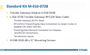
Standard Kit M-010-0728 Trimble Gateway Module E-006-0638 L-016-0728 Trimble Gateway RP1226 Main Cable – Trimble Gateway 44-Pin Head. – RP1226 for Power/Engine Data Connection to newer trucks or adapters for older vehicles. – Power/Ignition/Ground Connector for Displays. – Two RS232 Connections. – Two discrete inputs.
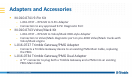
Adapters and Accessories M-010-0741 9-Pin Kit – L-016-0737 – RP1226 to 9-Pin Adapter – Connection to any approved 9-Pin Diagnostic Port M-010-0743 Volvo/Mack Kit – L-016-0737 – RP1226 to Volvo/Mack OBD-style Adapter – Connection to Volvo/Mack diagnostic port on pre-2018 Volvo/Mack trucks with Volvo/Mack engine L-016-0727 Trimble Gateway/PMG Adapter – Connects a Trimble Gateway device to an existing PMG Main Cable, replacing the PMG L-016-0734 Trimble Gateway/PMG Dual Adapter – A “Y” connector to
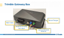
Trimble Gateway Box Mount Flanges Main Cable Ethernet Currently Not Used Optional External Antenna
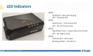
LED Indicators LED1 – Solid Red = ON and Charging – Off = Powered Off 1 2 3 4 LED2 – Solid Green = Cell Connected – Off = No Cell Connection LED3 – Rapid Blue Flash = Engine Data Connected – Off = No Engine Data LED4 – Solid Amber = GPS Fixed – Blinking Amber = No GPS Fix
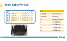
Main Cable Pin-out 1 10 A B C D 31 40 Pin A and B Input Power C and D Ground 31 Ignition Sense 6 J1708 High 7 J1708 Low 36 J1939 High 35 J1939 Low
Federal Communication Commission Interference Statement This device complies with Part 15 of the FCC Rules. Operation is subject to the following two conditions: (1) This device may not cause harmful interference, and (2) this device must accept any interference received, including interference that may cause undesired operation. This equipment has been tested and found to comply with the limits for a Class B digital device, pursuant to Part 15 of the FCC Rules.