
Trina Allmax M Plus Solar Module Installation Manual (IEC-UL)
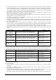
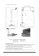
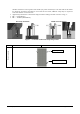
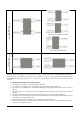
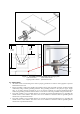
Table Of Contents

Date: April, 2016 DOC: PS-M-0434 A Page - 10 - of 15
Figure 3. PV module installed with Single-axis Tracing System
1) M6 Stainless Bolt 2) Flat Stainless Washer
3
) Spring Stainless Washer 4) HEX Stainless Nut
6.2 GROUNDING
• All module frames and mounting racks must be properly grounded in accordance with appropriate respective
National Electrical Code.
• Proper grounding is achieved by bonding the module frame(s) and all metallic structural members together
continuously using a suitable grounding conductor. The grounding conductor or strap may be copper, copper
alloy, or any other material acceptable for use as an electrical conductor per respective National Electrical
Codes. The grounding conductor must then make a connection to earth using a suitable earth ground electrode.
• Trina Solar modules can be installed with the use of third party listed grounding devices for grounding the
metallic frames of PV modules. The devices have to be installed in accordance with the grounding device
manufacturer’s specified instructions.
• Trina Solar modules can be installed with the use of third party listed grounding devices for grounding the
metallic frames of PV modules. The devices have to be installed in accordance with the grounding device
manufacturer’s specified instructions.
4
3
2
1
Φ7*10mm(0.28*0.39in)
INSTALLING HOLES
778mm
(30.6in)
1956mm
(77.0in)