INSTALLATION MANUAL IEC & UL version The Honey/Allmax Module The Honey Plus Module The Tallmax Module The Honey M Module The Honey M Plus Module The Tallmax M Plus Module The Trinasmart Module The Trinaswitch Module The Trinapeak Module The Splitmax Modue The Quadmax Module The Airmax Module The Spacemax Module Date: April, 2016 DOC: PS-M-0434 A TSM-PC05A TSM-PC05A.05 TSM-PC05A.08 TSM-PD05 TSM-PD05.05 TSM-PD05.08 TSM-PE05A TSM-PE05A.08 TSM-PC05A(II) TSM-PC05A.
Table of Content 1. DISCLAIMER OF LIABILITY ........................................................................................................... - 3 - 2. SAFETY PRECAUTIONS .................................................................................................................... - 3 - 3. UNPACKING AND STORAGE ........................................................................................................... - 5 3.1 4. PRODUCT IDENTIFICATION ...................................
1. DISCLAIMER OF LIABILITY • The installation, handling and use of Trina Solar crystalline modules are beyond company control. Trina Solar does not assume any responsibility for loss, damage, injury or expense resulting from the improper installation, handling, use or maintenance. • Trina Solar assumes no responsibility for any infringement of patents or other rights of third parties that may result from use of the module. No license is granted by implication or under any patent or patent rights.
• Common hardware items such as nuts, bolts, star washers, lock washers and the like have not been evaluated for electrical conductivity or for use as grounding devices and should be used only for maintaining mechanical connections and holding electrical grounding devices in the proper position for electrical conductivity.
the module is mounted with hardware that has been tested and evaluated with the module under this standard or by a field Inspection certifying that the installed module complies with the requirements of UL1703. 3. UNPACKING AND STORAGE • At time of receipt, verify that the product delivered is in fact the product ordered. The product name, subname, and serial number of each laminate are clearly marked on the outside of each packing box.
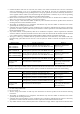
max under UL1703 standard) *Notes: -The modules have been evaluated by TUV according to IEC61215 for a maximum positive or negative design loading of below 550Kg/m² (5400Pa),by UL according to UL 1703, below 30lbs.ft2. -The mechanical load bearing is dependent upon the mounting methods used and failure to follow the instructions of this manual may result in different capabilities to withstand snow and wind loads.
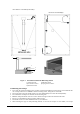
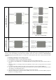
outer diameter of 20-24mm(0.79-0.94in). Dimension of DC06.08(II) Drain hole 1 2 3 4 5 Figure 1. PV module installed with Bolt fitting method 1) Aluminum Frame 3) Flat Stainless Washer 5) HEX Stainless Nut 2) M8 Stainless Bolt 4) Spring Stainless Washer B. Mounting with Clamps • Trina Solar has tested its modules with a number of clamps from different manufacturers and recommends the use of clamps which have an EPDM or similar insulating washer, fixing bolt of at least M6.
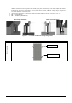
should be attached on each long sides of the module (for portrait orientation) or each short sides of the module (for landscape orientation). Depending on local wind and snow loads, additional clamps may be required to ensure that modules can bear the load. • Applied torque should refer to mechanical design standard according to the bolt customer is using, ex: • M6 ---- 9 N.m(70lbf.in) • M8 ---- 16-20N.m(140-180lbf.in) Middle Clamp installation End Clamp installation Figure 2.
Attachment to the long frame Clamping system This is Only for TSM-DC03A.08(II) Attachment to the short frame Clamping system This is Only for TSM-PC05B Other mounting configurations can be used. However, failure to comply with the above recommendations will result in a lowering of the load handling (snow/wind load) capabilities below the product specification 5400/2400Pa(IEC), 5400/3800Pa(UL1703) and product failure as a result of an overload situation will not be covered by the Trina Solar warranty.
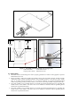
778mm (30.6in) 1956mm (77.0in) 1 2 Φ7*10mm(0.28*0.39in) INSTALLING HOLES 3 4 Figure 3. PV module installed with Single-axis Tracing System 1) M6 Stainless Bolt 3) Spring Stainless Washer 2) Flat Stainless Washer 4) HEX Stainless Nut 6.2 GROUNDING • All module frames and mounting racks must be properly grounded in accordance with appropriate respective National Electrical Code.
• Please refer to the “Product Catalogue” link for detailed grounding hole location and size at www.trinasolar.com. • We also recommend using the following methods to ground installation properly under UL investigation, Method 1: Tyco grounding bolt # 2058729-1: • • • • • • • • • 1 2 3 4 5 Figure 4. Tyco grounding bolt # 2058729-1 1) Wire bolt and slot 3) Aluminum frame 5) Hex Nut 2) Mounting wash hex nut 4) 0.006 to 0.
nut. • Electrical contact is made by penetrating the anodized coating of the aluminum frame, and tightening the mounting hex nut (come with the star washer) to the proper torque of 25lbf.in. • Grounding wire size (6 to 12 AWG solid bare copper) should be selected and installed underneath the wire binding bolt. • The wire binding bolt should be tightened to the proper torque of 45lbf.in. • The Tyco grounding bolt is only listed for use with 6 to 12 AWG bare solid copper wire.
N No modules in series Voc Open circuit voltage of each module (refer to product label or data sheet) TCvoc Thermal coefficient of open circuit voltage for the module (refer to data sheet) Tmin The lowest ambient temperature • Each module have two standards 90°C sunlight resistant output cables each terminated with plug & play connectors. The wire type and gauge of the output cables are 1000V (For TSM-PE05A.**, PE14A.** which are 1500V DC) rated PV Wire cable and are 12AWG in size.
can be applied to any Trina product. Alternatively, we recommend the use of an inverter that includes a transformer as well as proper grounding of the negative DC leg of the PV array. • Choose inverters with isolation transformers in hot and wet areas (such as shores, wetlands), to ensure proper module function under positive voltage. 8.
In the event that a module is damaged (broken glass or scratch on back sheet) and needs to be replaced then Observe the safety precautions listed earlier in the manual Wear cut resistant gloves and other personal protective equipment required for the particular installation. Isolate the impacted array string to prevent current flow before attempting to remove the module. Disconnect the connectors of the affected module using the related disconnect tool provided by suppliers.