MECHATRONIC DRIVES WITH STEPPER MOTOR PANdrives V 1.03 HARDWARE MANUAL + + TMCM-1180 PD86-1180 1-axis stepper controller / driver 5.5A RMS/ 24 or 48V DC USB, RS232, RS485, and CAN + TRINAMIC Motion Control GmbH & Co. KG Hamburg, Germany www.trinamic.
TMCM-1180 and PD86-1180 Hardware Manual (V1.03 / 2011-DEC-02) Table of contents 1 2 3 4 Life support policy ....................................................................................................................................................... 3 Features ........................................................................................................................................................................... 4 Order codes .....................................................
TMCM-1180 and PD86-1180 Hardware Manual (V1.03 / 2011-DEC-02) 1 Life support policy TRINAMIC Motion Control GmbH & Co. KG does not authorize or warrant any of its products for use in life support systems, without the specific written consent of TRINAMIC Motion Control GmbH & Co. KG.
TMCM-1180 and PD86-1180 Hardware Manual (V1.03 / 2011-DEC-02) 4 2 Features The PD86-1180 is a full mechatronic device consisting of a NEMA 34 (flange size 86mm) stepper motor, controller/driver electronics and integrated encoder. Applications Powerful single-axis stepper motor solutions Encoder feedback for high reliability operation Electrical data Supply voltage: +24V DC or +48V DC nominal Motor current: up to 5.5A RMS (programmable) PANdrive motor Two phase bipolar stepper motor with up to 5.
TMCM-1180 and PD86-1180 Hardware Manual (V1.03 / 2011-DEC-02) 5 3 Order codes Cables are not included. Add the appropriate cable loom to your order if required. Order code TMCM-1180 (-option) PD86-3-1180 (-option) Description TMCM-1180 with coolStep™, sensOstep™ PD86-3-1180 with coolStep™, sensOstep™, 7.0 Nm Table 3.1: PANdrive or module order codes Option -TMCL -CANopen Firmware TMCL firmware CANopen firmware Table 3.
TMCM-1180 and PD86-1180 Hardware Manual (V1.03 / 2011-DEC-02) 6 4 Mechanical and electrical interfacing 4.1 TMCM-1180 dimensions and mounting holes The dimensions of the controller/driver board (TMCM-1180) are approx. 86mm x 86mm in order to fit to the back side of the 86mm stepper motor. The TMCM-1180 is 21.5mm high without matching connectors. There are four mounting holes for M4 screws. 85.9 4.55 67.45 8 2 8 2 R5.9 M4 TMCM-1180 85.9 81.35 72 67.45 18.45 13.9 4.55 13.9 18.45 72 81.35 Figure 4.
TMCM-1180 and PD86-1180 Hardware Manual (V1.03 / 2011-DEC-02) 7 4.2 PD86-1180 dimensions and motor specifications The PD86-1180 includes the TMCM-1180 stepper motor controller/driver electronic module, a magnetic encoder based on sensOstep™ technology and an 86mm flange size bipolar hybrid stepper motor. 4.2.1 Dimensions of PD86-3-1180 96 4.1 22.5 max 1.4 17 1.1 25 73.02±0.05 12.7 11.6 85.85 31.75±1 1.52 8.38 69.5±0.2 85.9 73.02±0.05 11.6 12.7 4 x ø 5.5 400 min. Figure 4.
TMCM-1180 and PD86-1180 Hardware Manual (V1.03 / 2011-DEC-02) 4.2.2 Motor specifications of QSH8618-96-55-700 Specifications Units Wiring Rated Voltage V Rated Phase Current (nominal) A Phase Resistance at 20°C Ω Phase Inductance (typ.) mH Holding Torque (typ.) Nm Detent Torque Nm Rotor Inertia gcm2 Weight (Mass) Kg Insulation Class Insulation Resistance Ω Dialectic Strength (for one VAC minute) Connection Wires N° Max applicable Voltage V Step Angle ° Step angle Accuracy % Flange Size (max.
TMCM-1180 and PD86-1180 Hardware Manual (V1.03 / 2011-DEC-02) 9 4.2.3 Torque figure of QSH8618-96-55-700 The torque figure details the motor torque characteristics for full step operation in order to allow simple comparison. For full step operation there are always a number of resonance points (with less torque) which are not depicted. These will be minimized by microstep operation. Testing conditions: 48V; 5,5A Torque 6 Full step [Nm] 5 4 3 2 1 0 100 1000 Figure 4.
TMCM-1180 and PD86-1180 Hardware Manual (V1.03 / 2011-DEC-02) 10 4.3 Connectors of TMCM-1180 The controller/driver board for the PD86-1180 offers eight connectors including the motor connector which is used internally for attaching the motor coils to the electronics. In addition to the power connector there are two connectors for serial communication (one for mini-USB and one for RS232/RS485/CAN) and two connectors for additional input and output signals.
TMCM-1180 and PD86-1180 Hardware Manual (V1.03 / 2011-DEC-02) 11 4.3.1 Power connector This module offers separate power supply inputs for digital logic (connector pin 2) and driver/power stage (connector pin 1). Both supply inputs use common ground connections (connector pin 3 and 4). This way, power supply for the driver stage may be switched off while still maintaining position and status information when keeping digital logic supply active.
TMCM-1180 and PD86-1180 Hardware Manual (V1.03 / 2011-DEC-02) 12 4.3.2 Serial communication connector A 2mm pitch 8 pin JST B8B-PH-K connector is used for serial communication. With this connector the module supports RS232, RS485 and CAN communication. Mating connector housing: PHR-8 Mating connector contacts: SPH-002T-P0.5S.
TMCM-1180 and PD86-1180 Hardware Manual (V1.03 / 2011-DEC-02) 13 4.3.4 Output connector A 2mm pitch 4 pin JST B4B-PH-K connector is used for connecting the two general purpose outputs and the driver stage hardware shutdown input pin to the unit. Attention: In order to enable the motor driver stage connect /Shutdown (pin 2) to +ULogic (pin 1)! Mating connector housing: PHR-4 Mating connector contacts: SPH-002T-P0.
TMCM-1180 and PD86-1180 Hardware Manual (V1.03 / 2011-DEC-02) 14 4.3.5 Input connector A 2mm pitch 6 pin JST B6B-PH-K connector is used for connecting general purpose inputs, home and stop switches to the unit. Mating connector housing: PHR-6 Mating connector contacts: SPH-002T-P0.
TMCM-1180 and PD86-1180 Hardware Manual (V1.03 / 2011-DEC-02) 15 4.3.5.1 Left and right limit switches The TMCM-1180 can be configured so that a motor has a left and a right limit switch (Figure 4.9). The motor stops when the traveler has reached one of the limit switches. REF _ R _x REF _ L _x motor right stop switch left stop switch traveler Figure 4.9: Left and right limit switches 4.3.5.
TMCM-1180 and PD86-1180 Hardware Manual (V1.03 / 2011-DEC-02) 16 4.3.6 Step/Direction connector A 2mm pitch 4 pin JST B4B-PH-K connector is used for connecting the Step/Dir interface. Mating connector housing: PHR-4 Mating connector contacts: SPH-002T-P0.5S 1 4 Pin 1 2 3 4 Label OC_COM OC_EN OC_STEP OC_DIR Description Common supply / opto-coupler (+5V .. +24V) Enable signal Step signal Direction signal Table 4.5: Step/Dir connector C 4k75 EN +3.
TMCM-1180 and PD86-1180 Hardware Manual (V1.03 / 2011-DEC-02) 17 4.3.7 Encoder connector A 2mm pitch 5 pin JST B5B-PH-K connector is used for connecting the Encoder. Mating connector housing: PHR-5 Mating connector contacts: SPH-002T-P0.5S 1 Pin 1 2 3 4 5 5 Label ENC_A ENC_B ENC_N GND +5V_output Description Encoder A-channel Encoder B-channel Encoder N-channel Power and signal ground +5V output for encoder power supply (max. 100mA) Table 4.
TMCM-1180 and PD86-1180 Hardware Manual (V1.03 / 2011-DEC-02) 18 4.3.8 Motor connector and specifications A 3.96mm pitch 4 pin JST B4P-VH connector is used for motor connection. Both motor coil windings (bipolar stepper motor) are connected to this connector. Mating connector housing: VHR-4N Mating connector contacts: BVH-21T-P1.1 1 4 Pin Label Description 1 OA1 Motor coil A 2 3 4 OA2 OB1 OB2 Motor coil A Motor coil B Motor coil B Table 4.
TMCM-1180 and PD86-1180 Hardware Manual (V1.03 / 2011-DEC-02) 19 6 Operational ratings The operational ratings shown below should be used as design values. In no case should the maximum values been exceeded during operation.
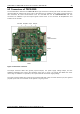
TMCM-1180 and PD86-1180 Hardware Manual (V1.03 / 2011-DEC-02) 20 7.1 System architecture The TMCM-1180 integrates a microcontroller with the TMCL™ (Trinamic Motion Control Language) operating system. The motion control real-time tasks are realized by the TMC428. 7.1.1 Microcontroller On this module, the Atmel AT91SAM7X256 is used to run the TMCL™ operating system and to control the TMC428. The CPU has 256KB flash memory and a 64KB RAM.
TMCM-1180 and PD86-1180 Hardware Manual (V1.03 / 2011-DEC-02) 21 The coolStep™ current regulator allows to control the reaction of the driver to increasing or decreasing load. The internal regulator uses two thresholds to determine the minimum and the maximum load angle for optimum motor operation. The current increment speed and the current decrement speed can be adapted to the application.
TMCM-1180 and PD86-1180 Hardware Manual (V1.
TMCM-1180 and PD86-1180 Hardware Manual (V1.03 / 2011-DEC-02) 23 9 TMCL™ TMCL™, the TRINAMIC Motion Control Language, is described in separate documentations, which refer to the specific products (e.g. TMCM-1180 TMCL™ Firmware Manual). The manuals are provided on www.trinamic.com. Please refer to these source for updated data sheets and application notes. 10 CANopen The TMCM-1180 module should also be used with the CANopen protocol in future versions.
TMCM-1180 and PD86-1180 Hardware Manual (V1.03 / 2011-DEC-02) 24 11 Revision history 11.1 Document revision Version Date Author GE – Göran Eggers SD – Sonja Dwersteg Description Initial version New hardware included New engineering detail drawings. Functional and operational descriptions added. New front page, minor changes Minor changes Order codes new, minor changes 0.90 0.91 2009-AUG-04 2009-NOV-11 GE GE 1.00 2010-JUN-28 SD 1.01 1.02 1.