MODULE FOR STEPPER MOTORS MODULE Firmware Version V1.20 TMCL™ FIRMWARE MANUAL + + TMCM-1161 1-Axis Stepper Controller / Driver Up to 2.8A RMS / 24V DC USB, RS485, and RS232 + UNIQUE FEATURES: TRINAMIC Motion Control GmbH & Co. KG Hamburg, Germany www.trinamic.
TMCM-1161 TMCL Firmware V1.19 Manual (Rev. 1.04 / 2012-NOV-19) Table of contents 1 2 Features........................................................................................................................................................................... 4 Putting the Module into Operation ........................................................................................................................ 6 2.1 Basic Set-Up .....................................................................
TMCM-1161 TMCL Firmware V1.19 Manual (Rev. 1.04 / 2012-NOV-19) 6 Hints and Tips ............................................................................................................................................................. 65 6.1 Reference Search ............................................................................................................................................... 65 6.2 Changing the Prescaler Value of an Encoder .......................................................
TMCM-1161 TMCL Firmware V1.19 Manual (Rev. 1.04 / 2012-NOV-19) 1 Features The TMCM-1161 is a single axis controller/driver module for 2-phase bipolar stepper motors with state of the art feature set. It is highly integrated, offers a convenient handling and can be used in many decentralized applications. The board can be mounted on the back of NEMA23 (57mm flange size) and NEMA24 (60mm flange size) stepper motors and has been designed for coil currents up to 2.8A RMS and 24V DC supply voltage.
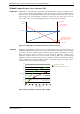
TMCM-1161 TMCL Firmware V1.19 Manual (Rev. 1.04 / 2012-NOV-19) 5 TRINAMICS UNIQUE FEATURES – EASY TO USE WITH TMCL stallGuard2™ stallGuard2 is a high-precision sensorless load measurement using the back EMF on the coils. It can be used for stall detection as well as other uses at loads below those which stall the motor. The stallGuard2 measurement value changes linearly over a wide range of load, velocity, and current settings. At maximum motor load, the value goes to zero or near to zero.
TMCM-1161 TMCL Firmware V1.19 Manual (Rev. 1.04 / 2012-NOV-19) 2 Putting the Module into Operation Here you can find basic information for putting your TMCM-1161 into operation. If you are already common with TRINAMICs modules you may skip this chapter.
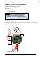
TMCM-1161 TMCL Firmware V1.19 Manual (Rev. 1.04 / 2012-NOV-19) 1. 7 Connect power supply and choose your interface a) Connect RS232 or RS485 and power supply Pin 1 2 3 4 5 6 Label GND VCC RS485A+ RS485BRS232_TxD RS232_RxD Description Module and signal ground 10… 30V DC power supply / nom.
TMCM-1161 TMCL Firmware V1.19 Manual (Rev. 1.04 / 2012-NOV-19) 4. Switch ON the power supply Turn power ON. The green LED for power lights up slowly and the motor is powered but in standstill now. If this does not occur, switch power OFF and check your connections as well as the power supply. 2.1.2 Start the TMCL-IDE Software Development Environment The TMCL-IDE is available on www.trinamic.com. Installing the TMCL-IDE: Make sure the COM port you intend to use is not blocked by another program.
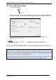
TMCM-1161 TMCL Firmware V1.19 Manual (Rev. 1.04 / 2012-NOV-19) 2.2 Using TMCL Direct Mode 1. Start TMCL Direct Mode. Direct Mode 2. If the communication is established the TMCM-1161 is automatically detected. If the module is not detected, please check all points above (cables, interface, power supply, COM port, baud rate). 3. Issue a command by choosing Instruction, Type (if necessary), Motor, and Value and click Execute to send it to the module.
TMCM-1161 TMCL Firmware V1.19 Manual (Rev. 1.04 / 2012-NOV-19) 2.2.1 10 Important Motor Settings There are some axis parameters which have to be adjusted right in the beginning after installing your module. Please set the upper limiting values for the speed (axis parameter 4), the acceleration (axis parameter 5), and the current (axis parameter 6). Further set the standby current (axis parameter 7) and choose your microstep resolution with axis parameter 140.
TMCM-1161 TMCL Firmware V1.19 Manual (Rev. 1.04 / 2012-NOV-19) 2.3 Testing with a Simple TMCL Program Type in the following program: Loop: ROL 0, 500 WAIT TICKS, 0, 500 MST 0 ROR 0, 500 WAIT TICKS, 0, 500 MST 0 //Rotate motor 0 with speed 500 SAP 4, 0, 500 SAP 5, 0, 50 MVP ABS, 0, 10000 WAIT POS, 0, 0 MVP ABS, 0, -10000 WAIT POS, 0, 0 JA Loop //Set max. Velocity //Set max.
TMCM-1161 TMCL Firmware V1.19 Manual (Rev. 1.04 / 2012-NOV-19) 12 3 TMCL and the TMCL-IDE: Introduction As with most TRINAMIC modules the software running on the microprocessor of the TMCM-1161 consists of two parts, a boot loader and the firmware itself. Whereas the boot loader is installed during production and testing at TRINAMIC and remains untouched throughout the whole lifetime, the firmware can be updated by the user.
TMCM-1161 TMCL Firmware V1.19 Manual (Rev. 1.04 / 2012-NOV-19) 3.1.1 13 Checksum Calculation As mentioned above, the checksum is calculated by adding up all bytes (including the module address byte) using 8-bit addition.
TMCM-1161 TMCL Firmware V1.19 Manual (Rev. 1.04 / 2012-NOV-19) 3.2.1 14 Status Codes The reply contains a status code. The status code can have one of the following values: Code 100 101 1 2 3 4 5 6 Meaning Successfully executed, no error Command loaded into TMCL program EEPROM Wrong checksum Invalid command Wrong type Invalid value Configuration EEPROM locked Command not available 3.3 Standalone Applications The module is equipped with a TMCL memory for storing TMCL applications.
TMCM-1161 TMCL Firmware V1.19 Manual (Rev. 1.04 / 2012-NOV-19) 15 3.4 TMCL Command Overview In this section a short overview of the TMCL commands is given. 3.4.
TMCM-1161 TMCL Firmware V1.19 Manual (Rev. 1.04 / 2012-NOV-19) 3.4.2 16 Commands Listed According to Subject Area 3.4.2.1 Motion Commands These commands control the motion of the motor. They are the most important commands and can be used in direct mode or in standalone mode. Mnemonic ROL ROR MVP MST RFS SCO CCO GCO Command number 2 1 4 3 13 30 32 31 Meaning Rotate left Rotate right Move to position Motor stop Reference search Store coordinate Capture coordinate Get coordinate 3.4.2.
TMCM-1161 TMCL Firmware V1.19 Manual (Rev. 1.04 / 2012-NOV-19) 17 3.4.2.5 Calculation Commands These commands are intended to be used for calculations within TMCL™ applications. Although they could also be used in direct mode it does not make much sense to do so.
TMCM-1161 TMCL Firmware V1.19 Manual (Rev. 1.04 / 2012-NOV-19) 3.4.2.6.3 18 Interrupt Vectors The following table shows all interrupt vectors that can be used. Interrupt number 0 1 2 3 15 21 27 28 39 40 255 3.4.2.6.4 Interrupt type Timer 0 Timer 1 Timer 2 Target position reached stallGuard2 Deviation Left stop switch Right stop switch Input change 0 Input change 1 Global interrupts Further Configuration of Interrupts Some interrupts need further configuration (e.g.
TMCM-1161 TMCL Firmware V1.19 Manual (Rev. 1.04 / 2012-NOV-19) 19 In the example above, the interrupt numbers are used directly. To make the program better readable use the provided include file Interrupts.inc. This file defines symbolic constants for all interrupt numbers which can be used in all interrupt commands. The beginning of the program above then looks like the following: #include Interrupts.
TMCM-1161 TMCL Firmware V1.19 Manual (Rev. 1.04 / 2012-NOV-19) 20 3.5 Commands The module specific commands are explained in more detail on the following pages. They are listed according to their command number. 3.5.1 ROR (rotate right) With this command the motor will be instructed to rotate with a specified velocity in right direction (increasing the position counter). Internal function: First, velocity mode is selected. Then, the velocity value is transferred to axis parameter #0 (target velocity).
TMCM-1161 TMCL Firmware V1.19 Manual (Rev. 1.04 / 2012-NOV-19) 3.5.2 21 ROL (rotate left) With this command the motor will be instructed to rotate with a specified velocity (opposite direction compared to ROR, decreasing the position counter). Internal function: First, velocity mode is selected. Then, the velocity value is transferred to axis parameter #0 (target velocity). The module is based on the TMC429 stepper motor controller and the TMC262 power driver.
TMCM-1161 TMCL Firmware V1.19 Manual (Rev. 1.04 / 2012-NOV-19) 3.5.3 22 MST (motor stop) With this command the motor will be instructed to stop with a soft stop. Internal function: The axis parameter target velocity is set to zero. Related commands: ROL, ROR, SAP, GAP Mnemonic: MST 0 Binary representation: INSTRUCTION NO.
TMCM-1161 TMCL Firmware V1.19 Manual (Rev. 1.04 / 2012-NOV-19) 3.5.4 23 MVP (move to position) With this command the motor will be instructed to move to a specified relative or absolute position. It will use the acceleration/deceleration ramp and the positioning speed programmed into the unit. This command is non-blocking – that is, a reply will be sent immediately after command interpretation and initialization of the motion controller.
TMCM-1161 TMCL Firmware V1.19 Manual (Rev. 1.04 / 2012-NOV-19) 3.5.5 24 SAP (set axis parameter) With this command most of the motion control parameters of the module can be specified. The settings will be stored in SRAM and therefore are volatile. That is, information will be lost after power off. Please use command STAP (store axis parameter) in order to store any setting permanently. For a table with parameters and values which can be used together with this command please refer to chapter 4.
TMCM-1161 TMCL Firmware V1.19 Manual (Rev. 1.04 / 2012-NOV-19) 3.5.6 25 GAP (get axis parameter) Most parameters of the TMCM-1161 can be adjusted individually for the axis. With this parameter they can be read out. In standalone mode the requested value is also transferred to the accumulator register for further processing purposes (such as conditioned jumps). In direct mode the value read is only output in the value field of the reply (without affecting the accumulator).
TMCM-1161 TMCL Firmware V1.19 Manual (Rev. 1.04 / 2012-NOV-19) 3.5.7 STAP 26 (store axis parameter) An axis parameter previously set with a Set Axis Parameter command (SAP) will be stored permanent. Most parameters are automatically restored after power up (refer to axis parameter list in chapter 4). For a table with parameters and values which can be used together with this command please refer to chapter 4.
TMCM-1161 TMCL Firmware V1.19 Manual (Rev. 1.04 / 2012-NOV-19) 3.5.8 27 RSAP (restore axis parameter) For all configuration-related axis parameters non-volatile memory locations are provided. By default, most parameters are automatically restored after power up (refer to axis parameter list in chapter 4). A single parameter that has been changed before can be reset by this instruction also. For a table with parameters and values which can be used together with this command please refer to chapter 4.
TMCM-1161 TMCL Firmware V1.19 Manual (Rev. 1.04 / 2012-NOV-19) 3.5.9 28 SGP (set global parameter) With this command most of the module specific parameters not directly related to motion control can be specified and the TMCL user variables can be changed. Global parameters are related to the host interface, peripherals or application specific variables. The different groups of these parameters are organized in banks to allow a larger total number for future products.
TMCM-1161 TMCL Firmware V1.19 Manual (Rev. 1.04 / 2012-NOV-19) 29 3.5.10 GGP (get global parameter) All global parameters can be read with this function. Global parameters are related to the host interface, peripherals or application specific variables. The different groups of these parameters are organized in banks to allow a larger total number for future products. Currently, only bank 0 and 1 are used for global parameters, and bank 2 is used for user variables.
TMCM-1161 TMCL Firmware V1.19 Manual (Rev. 1.04 / 2012-NOV-19) 30 3.5.11 STGP (store global parameter) This command is used to store TMCL user variables permanently in the EEPROM of the module. Some global parameters are located in RAM memory, so without storing modifications are lost at power down. This instruction enables enduring storing. Most parameters are automatically restored after power up.
TMCM-1161 TMCL Firmware V1.19 Manual (Rev. 1.04 / 2012-NOV-19) 31 3.5.12 RSGP (restore global parameter) With this command the contents of a TMCL user variable can be restored from the EEPROM. For all configuration-related axis parameters, non-volatile memory locations are provided. By default, most parameters are automatically restored after power up. A single parameter that has been changed before can be reset by this instruction.
TMCM-1161 TMCL Firmware V1.19 Manual (Rev. 1.04 / 2012-NOV-19) 32 3.5.13 RFS (reference search) The TMCM-1161 has a built-in reference search algorithm which can be used. The reference search algorithm provides switching point calibration and three switch modes. The status of the reference search can also be queried to see if it has already finished. (In a TMCL program it is better to use the WAIT command to wait for the end of a reference search.
TMCM-1161 TMCL Firmware V1.19 Manual (Rev. 1.04 / 2012-NOV-19) 33 3.5.14 SIO (set input / output) - SIO sets the status of the general digital output either to low (0) or to high (1). Bank 2 is used for this purpose. SIO is used to switch the pull-up resistors for all digital inputs ON (1) and OFF (0). Bank 0 is used for this purpose. Internal function: the passed value is transferred to the specified output line.
TMCM-1161 TMCL Firmware V1.19 Manual (Rev. 1.04 / 2012-NOV-19) 34 ADDRESSING BOTH OUTPUT LINES WITH ONE SIO COMMAND: - Set the type parameter to 255 and the bank parameter to 2. The value parameter must then be set to a value between 0… 255, where every bit represents one output line. Furthermore, the value can also be set to -1. In this special case, the contents of the lower 8 bits of the accumulator are copied to the output pins. Example: Set all output pins high.
TMCM-1161 TMCL Firmware V1.19 Manual (Rev. 1.04 / 2012-NOV-19) 35 3.5.15 GIO (get input /output) With this command the status of the two available general purpose inputs of the module can be read out. The function reads a digital or analogue input port. Digital lines will read 0 and 1, while the ADC channels deliver their 12 bit result in the range of 0… 4095.
TMCM-1161 TMCL Firmware V1.19 Manual (Rev. 1.04 / 2012-NOV-19) 36 1 Interface USB In/Out 1 1 Motor 1 Figure 3.2 Connectors 3.5.15.1 I/O Bank 0 – Digital Inputs: The ADIN lines can be read as digital or analogue inputs at the same time. The analogue values can be accessed in bank 1. Pin 6 7 8 I/O port IN_1 IN_2 IN_3 Command GIO 0, 0, GIO 1, 0, GIO 2, 0, Range 0/1 0/1 0/1 READING ALL DIGITAL INPUTS WITH ONE GIO COMMAND: - Set the type parameter to 255 and the bank parameter to 0.
TMCM-1161 TMCL Firmware V1.19 Manual (Rev. 1.04 / 2012-NOV-19) 37 3.5.16 CALC (calculate) A value in the accumulator variable, previously read by a function such as GAP (get axis parameter) can be modified with this instruction. Nine different arithmetic functions can be chosen and one constant operand value must be specified. The result is written back to the accumulator, for further processing like comparisons or data transfer.
TMCM-1161 TMCL Firmware V1.19 Manual (Rev. 1.04 / 2012-NOV-19) 38 3.5.17 COMP (compare) The specified number is compared to the value in the accumulator register. The result of the comparison can for example be used by the conditional jump (JC) instruction. This command is intended for use in standalone operation only. The host address and the reply are only used to take the instruction to the TMCL program memory while the program loads down. It does not make sense to use this command in direct mode.
TMCM-1161 TMCL Firmware V1.19 Manual (Rev. 1.04 / 2012-NOV-19) 39 3.5.18 JC (jump conditional) The JC instruction enables a conditional jump to a fixed address in the TMCL program memory, if the specified condition is met. The conditions refer to the result of a preceding comparison. Please refer to COMP instruction for examples. This function is for standalone operation only. The host address and the reply are only used to take the instruction to the TMCL program memory while the program loads down.
TMCM-1161 TMCL Firmware V1.19 Manual (Rev. 1.04 / 2012-NOV-19) 40 3.5.19 JA (jump always) Jump to a fixed address in the TMCL program memory. This command is intended for standalone operation only. The host address and the reply are only used to take the instruction to the TMCL program memory while the program loads down. This command cannot be used in direct mode. Internal function: the TMCL program counter is set to the passed value.
TMCM-1161 TMCL Firmware V1.19 Manual (Rev. 1.04 / 2012-NOV-19) 41 3.5.20 CSUB (call subroutine) This function calls a subroutine in the TMCL program memory. It is intended for standalone operation only. The host address and the reply are only used to take the instruction to the TMCL program memory while the program loads down. This command cannot be used in direct mode. Internal function: The actual TMCL program counter value is saved to an internal stack, afterwards overwritten with the passed value.
TMCM-1161 TMCL Firmware V1.19 Manual (Rev. 1.04 / 2012-NOV-19) 42 3.5.21 RSUB (return from subroutine) Return from a subroutine to the command after the CSUB command. This command is intended for use in standalone mode only. The host address and the reply are only used to take the instruction to the TMCL program memory while the program loads down. This command cannot be used in direct mode. Internal function: The TMCL program counter is set to the last value of the stack.
TMCM-1161 TMCL Firmware V1.19 Manual (Rev. 1.04 / 2012-NOV-19) 43 3.5.22 WAIT (wait for an event to occur) This instruction interrupts the execution of the TMCL program until the specified condition is met. This command is intended for standalone operation only. The host address and the reply are only used to take the instruction to the TMCL program memory while the program loads down. This command cannot be used in direct mode.
TMCM-1161 TMCL Firmware V1.19 Manual (Rev. 1.04 / 2012-NOV-19) 44 3.5.23 STOP (stop TMCL program execution) This function stops executing a TMCL program. The host address and the reply are only used to transfer the instruction to the TMCL program memory. This command should be placed at the end of every standalone TMCL program. It is not to be used in direct mode. Internal function: TMCL instruction fetching is stopped. Related commands: none Mnemonic: STOP Binary representation: INSTRUCTION NO.
TMCM-1161 TMCL Firmware V1.19 Manual (Rev. 1.04 / 2012-NOV-19) 45 3.5.24 CALCX (calculate using the X register) This instruction is very similar to CALC, but the second operand comes from the X register. The X register can be loaded with the LOAD or the SWAP type of this instruction. The result is written back to the accumulator for further processing like comparisons or data transfer.
TMCM-1161 TMCL Firmware V1.19 Manual (Rev. 1.04 / 2012-NOV-19) 46 3.5.25 AAP (accumulator to axis parameter) The content of the accumulator register is transferred to the specified axis parameter. For practical usage, the accumulator has to be loaded e.g. by a preceding GAP instruction. The accumulator may have been modified by the CALC or CALCX (calculate) instruction. For a table with parameters and values which can be used together with this command please refer to chapter 4.
TMCM-1161 TMCL Firmware V1.19 Manual (Rev. 1.04 / 2012-NOV-19) 47 3.5.26 AGP (accumulator to global parameter) The content of the accumulator register is transferred to the specified global parameter. For practical usage, the accumulator has to be loaded e.g. by a preceding GAP instruction. The accumulator may have been modified by the CALC or CALCX (calculate) instruction. Note that the global parameters in bank 0 are EEPROM-only and thus should not be modified automatically by a standalone application.
TMCM-1161 TMCL Firmware V1.19 Manual (Rev. 1.04 / 2012-NOV-19) 48 3.5.27 CLE (clear error flags) This command clears the internal error flags. It is intended for use in standalone mode only and must not be used in direct mode. The following error flags can be cleared by this command (determined by the parameter): ALL: clear all error flags. ETO: clear the timeout flag.
TMCM-1161 TMCL Firmware V1.19 Manual (Rev. 1.04 / 2012-NOV-19) 49 3.5.28 Customer specific TMCL command extension (UF0… UF7/user function) The user definable functions UF0… UF7 are predefined, functions without topic for user specific purposes. Contact TRINAMIC for the customer specific programming of these functions. Internal function: Call user specific functions implemented in C by TRINAMIC. Related commands: none Mnemonic: UF0… UF7 Binary representation: INSTRUCTION NO.
TMCM-1161 TMCL Firmware V1.19 Manual (Rev. 1.04 / 2012-NOV-19) 50 3.5.30 TMCL Control Functions The following functions are for host control purposes only and are not allowed for standalone mode. In most cases, there is no need for the customer to use one of those functions (except command 139). They are mentioned here only for reasons of completeness. These commands have no mnemonics, as they cannot be used in TMCL programs.
TMCM-1161 TMCL Firmware V1.19 Manual (Rev. 1.04 / 2012-NOV-19) Special reply format of command 136: Type set to 0 - reply as a string: Byte index 1 2… 9 Contents Host Address Version string (8 characters, e.g. 1161V1.15) There is no checksum in this reply format! Type set to 1 - version number in binary format: - Please use the normal reply format. The version number is output in the value field of the reply in the following way: Byte index in value field 1 2 3 4 www.trinamic.
TMCM-1161 TMCL Firmware V1.19 Manual (Rev. 1.04 / 2012-NOV-19) 52 4 Axis parameters The following sections describe all axis parameters that can be used with the SAP, GAP, AAP, STAP and RSAP commands. Meaning of the letters in column Access: Access type R W E Related command(s) GAP SAP, AAP STAP, RSAP Description Parameter readable Parameter writable Parameter automatically restored from EEPROM after reset or power-on.
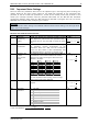
TMCM-1161 TMCL Firmware V1.19 Manual (Rev. 1.04 / 2012-NOV-19) 53 Number 7 Axis Parameter Standby current Description Range [Unit] The current limit two seconds after the motor 0… 255 has stopped. Acc. RWE 8 Target pos. reached Ref. switch status Right limit switch status Left limit switch status Right limit switch disable Left limit switch disable Minimum speed Indicates that the actual position equals the 0/1 target position. The logical state of the reference home 0/1 switch.
TMCM-1161 TMCL Firmware V1.19 Manual (Rev. 1.04 / 2012-NOV-19) Number 160 161 162 163 164 165 166 167 Axis Parameter Step interpolation enable Description Step interpolation is supported with a 16 microstep setting only. In this setting, each step impulse at the input causes the execution of 16 times 1/256 microsteps. This way, a smooth motor movement like in 256 microstep resolution is achieved.
TMCM-1161 TMCL Firmware V1.19 Manual (Rev. 1.04 / 2012-NOV-19) Number 169 Axis Parameter smartEnergy current down step 55 Description Range [Unit] Sets the number of stallGuard2™ readings 0… 3 above the upper threshold necessary for each current decrement of the motor current. Acc.
TMCM-1161 TMCL Firmware V1.19 Manual (Rev. 1.04 / 2012-NOV-19) Number 177 Axis Parameter short protection disable 178 Short detection timer 179 Vsense 180 smartEnergy actual current Description 0: Short to GND protection is on 1: Short to GND protection is disabled Use default value! 0: 3.2µs 1: 1.6µs 2: 1.2µs 3: 0.
TMCM-1161 TMCL Firmware V1.19 Manual (Rev. 1.04 / 2012-NOV-19) Number 196 Axis Parameter Distance end switches 200 Boost current 204 Freewheeling 206 207 208 Description Range [Unit] This parameter provides the distance between 0… 2.147.483.647 the end switches after executing the RFS command (mode 2 or 3). Current used for acceleration and deceleration 0… 255 phases. If set to 0 the same current as set by axis parameter 6 will be used.
TMCM-1161 TMCL Firmware V1.19 Manual (Rev. 1.04 / 2012-NOV-19) Number 254 Axis Parameter Step/dir mode Description 1 2 3 4 5 * Unit of acceleration: www.trinamic.
TMCM-1161 TMCL Firmware V1.19 Manual (Rev. 1.04 / 2012-NOV-19) 59 4.1 stallGuard2 The module is equipped with TMC262 motor driver chip. The TMC262 features load measurement that can be used for stall detection. stallGuard2 delivers a sensorless load measurement of the motor as well as a stall detection signal. The measured value changes linear with the load on the motor in a wide range of load, velocity and current settings. At maximum motor load the stallGuard2 value goes to zero.
TMCM-1161 TMCL Firmware V1.19 Manual (Rev. 1.04 / 2012-NOV-19) Number I6 I7 I168 I169 I171 I183 60 Axis parameter Description The maximum value is 255. This value means 100% of the maximum current of the module. The current adjustment is within the range 0… 255 and can be adjusted in 32 steps (0… absolute max. current (CS / 255 divided by eight; e.g. step 0 = 0… 7, step 1 = 8… 15 and so Current Scale) on).
TMCM-1161 TMCL Firmware V1.19 Manual (Rev. 1.04 / 2012-NOV-19) 61 5 Global parameters Global parameters are grouped into 4 banks: - bank bank bank bank 0 1 2 3 (global configuration of the module) (user C variables) (user TMCL variables) (interrupt configuration) Please use SGP and GGP commands to write and read global parameters. 5.1 Bank 0 Parameters with numbers from 64 on configure stuff like the serial address of the module RS232/RS485 baud rate. Change these parameters to meet your needs.
TMCM-1161 TMCL Firmware V1.19 Manual (Rev. 1.04 / 2012-NOV-19) Number 73 Parameter configuration EEPROM lock flag 75 telegram pause time 76 serial host address auto start mode 77 79 81 End switch polarity TMCL code protection 84 Coordinate storage 128 TMCL application status 129 download mode 130 132 TMCL program counter tick timer 133 random number Description Write: 1234 to lock the EEPROM, 4321 to unlock it. Read: 1=EEPROM locked, 0=EEPROM unlocked.
TMCM-1161 TMCL Firmware V1.19 Manual (Rev. 1.04 / 2012-NOV-19) 63 5.3 Bank 2 Bank 2 contains general purpose 32 bit variables for the use in TMCL applications. They are located in RAM and the first 56 variables can be stored permanently in EEPROM, also. After booting, their values are automatically restored to the RAM. Up to 256 user variables are available.
TMCM-1161 TMCL Firmware V1.19 Manual (Rev. 1.04 / 2012-NOV-19) 64 5.4 Bank 3 Bank 3 contains interrupt parameters. Some interrupts need configuration (e.g. the timer interval of a timer interrupt). This can be done using the SGP commands with parameter bank 3 (SGP , 3, ). The parameter number defines the priority of an interrupt. Interrupts with a lower number have a higher priority.
TMCM-1161 TMCL Firmware V1.19 Manual (Rev. 1.04 / 2012-NOV-19) 65 6 Hints and Tips This chapter gives some hints and tips on using the functionality of TMCL, for example how to use and parameterize the built-in reference point search algorithm or the incremental sensOstep encoder. Further you will find basic information about stallGuard2 and coolStep. 6.1 Reference Search The built-in reference search features switching point calibration and support of one or two reference switches.
TMCM-1161 TMCL Firmware V1.19 Manual (Rev. 1.04 / 2012-NOV-19) SAP 193, 0, 1 negative limit switch Search left stop switch only. SAP 193, 0, 2 negative limit switch positive limit switch Search right stop switch, then search left stop switch. SAP 193, 0, 3 negative limit switch positive limit switch Search right stop switch, then search left stop switch from both sides. SAP 193, 0, 4 negative limit switch Search left stop switch from both sides. www.trinamic.
TMCM-1161 TMCL Firmware V1.19 Manual (Rev. 1.04 / 2012-NOV-19) SAP 193, 0, 5 negative limit switch positive limit switch home switch Search home switch in negative direction, reverse the direction when left stop switch reached. SAP 193, 0, 6 negative limit switch positive limit switch home switch Search home switch in positive direction, reverse the direction when right stop switch reached. SAP 193, 0, 7 home switch Search home switch in positive direction, ignore end switches.
TMCM-1161 TMCL Firmware V1.19 Manual (Rev. 1.04 / 2012-NOV-19) 68 6.2 Changing the Prescaler Value of an Encoder The TMCM-1161 offers an integrated sensOstep encoder. The built-in encoder has 1024 steps/rotation. For the operation with encoder please consider the following hints: The encoder counter can be read by software and can be used to control the exact position of the motor. This also makes closed loop operation possible.
TMCM-1161 TMCL Firmware V1.19 Manual (Rev. 1.04 / 2012-NOV-19) 7 Life Support Policy TRINAMIC Motion Control GmbH & Co. KG does not authorize or warrant any of its products for use in life support systems, without the specific written consent of TRINAMIC Motion Control GmbH & Co. KG.
TMCM-1161 TMCL Firmware V1.19 Manual (Rev. 1.04 / 2012-NOV-19) 8 Revision History 8.1 Firmware Revision Version 1.15 1.16 1.19 Date 2012-FEB-28 2012-MAY-16 2012-JUN-25 Description Release Global parameter 84 added Global parameter 79 added 8.2 Document Revision Author Version Date 1.00 1.01 1.02 2011-JUN-30 2012-MAR-09 2012-MAY-17 SD SD SD 1.03 2012-JUL-30 SD 1.