MODULES FOR STEPPER MOTORS MODULES Hardware Version V1.0 HARDWARE MANUAL + + TMCM-1161 1-axis Stepper Controller / Driver up to 2.8 RMS / 24V DC USB, RS485, and RS232 + UNIQUE FEATURES: TRINAMIC Motion Control GmbH & Co. KG Hamburg, Germany www.trinamic.
TMCM-1161 V1.0 Hardware Manual (Rev. 1.12 / 2012-JUL-30) 2 Table of Contents 1 2 3 Features........................................................................................................................................................................... 3 Order Codes ................................................................................................................................................................... 5 Mechanical and Electrical Interfacing .............................
TMCM-1161 V1.0 Hardware Manual (Rev. 1.12 / 2012-JUL-30) 3 1 Features The TMCM-1161 is a single axis controller/driver module for 2-phase bipolar stepper motors with state of the art feature set. It is highly integrated, offers a convenient handling and can be used in many decentralized applications. The module can be mounted on the back of NEMA23 (57mm flange size) and NEMA24 (60mm flange size) stepper motors and has been designed for coil currents up to 2.8A RMS and 24V DC supply voltage.
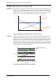
TMCM-1161 V1.0 Hardware Manual (Rev. 1.12 / 2012-JUL-30) 4 TRINAMICS UNIQUE FEATURES – EASY TO USE WITH TMCL stallGuard2™ stallGuard2 is a high-precision sensorless load measurement using the back EMF on the coils. It can be used for stall detection as well as other uses at loads below those which stall the motor. The stallGuard2 measurement value changes linearly over a wide range of load, velocity, and current settings. At maximum motor load, the value goes to zero or near to zero.
TMCM-1161 V1.0 Hardware Manual (Rev. 1.12 / 2012-JUL-30) 5 2 Order Codes Order code TMCM-1161 Description Single axis bipolar stepper motor controller / driver electronics with integrated sensOstep encoder and coolStep feature Size (mm3) 60 x 60 x 12 Table 2.
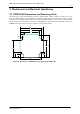
TMCM-1161 V1.0 Hardware Manual (Rev. 1.12 / 2012-JUL-30) 6 3 Mechanical and Electrical Interfacing 3.1 TMCM-1161 Dimensions and Mounting Holes The dimensions of the controller/driver board are approx. 60mm x 60mm x 12mm in order to fit on the back of a 60mm stepper motor. Maximum component height (height above PCB level) without mating connectors is around 8mm above PCB level and 2.5mm below PCB level.
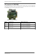
TMCM-1161 V1.0 Hardware Manual (Rev. 1.12 / 2012-JUL-30) 7 3.2 Connectors of TMCM-1161 The TMCM-1161 offers four connectors including the motor connector which is used for attaching the motor coils to the electronics. There are two connectors for serial communication (one for USB and one for RS232/RS485) and one connector for I/O signals and switches. 1 Interface 1 USB In/Out 1 Motor 1 Figure 3.2 Overview connectors Domain Interface / Power Motor In/Out USB Connector type JST B6B-EH-A, 2.
TMCM-1161 V1.0 Hardware Manual (Rev. 1.12 / 2012-JUL-30) 8 3.2.1 Interface and Power Supply Connector Pin 1 2 3 4 5 6 Label GND VCC RS485A+ RS485BRS232_TxD RS232_RxD Description Module and signal ground 10… 30V DC power supply / nom. 24V DC RS485 non-inverted bus signal RS485 inverted bus signal RS232 transmit data from module RS232 receive data to module Table 3.1 Connector for power supply and interfaces 3.2.1.
TMCM-1161 V1.0 Hardware Manual (Rev. 1.12 / 2012-JUL-30) 9 2. BUS TERMINATION: Especially for longer busses and/or multiple nodes connected to the bus and/or high communication speeds, the bus should be properly terminated at both ends. The PD-1161 does not integrate any termination resistor. Therefore, 120 Ohm termination resistors at both ends of the bus have to be added externally. 3.
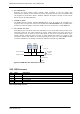
TMCM-1161 V1.0 Hardware Manual (Rev. 1.12 / 2012-JUL-30) 10 3.2.3 In/Out Connector Pin 1 2 3 4 5 Label GND VCC OUT_0 OUT_1 AIN_0 6 STOP_L/ STEP/ IN_1 7 STOP_R/ DIR/ IN_2 8 HOME/ ENABLE/ IN_3 Description Module ground (system and signal ground) 10… 30V DC power supply / nom. 24V DC General purpose output, open collector General purpose output, open collector Analog input, 0… 10V (analog to digital converter range) Digital input, +24V compatible, programmable internal pull-up.
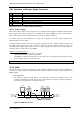
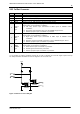
TMCM-1161 V1.0 Hardware Manual (Rev. 1.12 / 2012-JUL-30) 11 PU 1kO +5V / pull-up ON 0V / pull-up OFF IN_1/2/3 10kO +3.3V 47kO AIN_0 IN_1/2/3 GND GND GND Figure 3.4 Internal circuit of AIN_0 1nF 22kO 22kO 100nF AIN_0 GND GND Figure 3.5 Internal circuit of IN_1/2/3 3.2.3.1 Left and Right Limit Switches The TMCM-1161 can be configured so that a motor has a left and a right limit switch. The motor stops when the traveler has reached one of the limit switches.
TMCM-1161 V1.0 Hardware Manual (Rev. 1.12 / 2012-JUL-30) 12 4 Reset to Factory Defaults It is possible to reset the TMCM-1161 to factory default settings without establishing a communication link. This might be helpful in case communication parameters of the preferred interface have been set to unknown values or got accidentally lost. For this procedure two pads on the bottom side of the board have to be shortened (see figure 4.12). Please perform the following steps: 1. 2. 3. 4. 5. 6. 7.
TMCM-1161 V1.0 Hardware Manual (Rev. 1.12 / 2012-JUL-30) 13 5 On-board LEDs The board offers two LEDs in order to indicate board status. The function of both LEDs is dependent on the firmware version. With standard TMCL firmware the green LED should be slowly flashing during operation and the red LED should be off. When there is no valid firmware programmed into the board or during firmware update the red and green LEDs are permanently on.
TMCM-1161 V1.0 Hardware Manual (Rev. 1.12 / 2012-JUL-30) 14 6 Operational Ratings The operational ratings shown below should be used as design values. In no case should the maximum values been exceeded during operation.
TMCM-1161 V1.0 Hardware Manual (Rev. 1.12 / 2012-JUL-30) 15 7 Functional Description The TMCM-1161 is a highly integrated controller/driver module which can be controlled via several serial interfaces. Communication traffic is kept low since all time critical operations (e.g. ramp calculations) are performed on board. The nominal supply voltage of the unit is 24V DC. The module is designed for both, standalone operation and direct mode. Full remote control of device with feedback is possible.
TMCM-1161 V1.0 Hardware Manual (Rev. 1.12 / 2012-JUL-30) 16 8 TMCM-1161 Operational Description 8.1 Calculation: Velocity and Acceleration vs. Microstep and Fullstep Frequency The values of the parameters sent to the TMC429 do not have typical motor values like rotations per second as velocity. But these values can be calculated from the TMC429 parameters as shown in this section. PARAMETERS OF TMC429 Signal Description fCLK clock-frequency velocity a_max maximum acceleration divider for the velocity.
TMCM-1161 V1.0 Hardware Manual (Rev. 1.12 / 2012-JUL-30) 17 Example: Signal f_CLK velocity a_max pulse_div ramp_div usrs msf 16 MHz 1000 21 2048 32 fsf [Hz] a value 16 MHz 1000 1000 1 1 6 122070.31 26 1907.34Hz (16Mhz) 2 1000 2 11 29 122070.31Hz 119.21 MHz s MHz s 1.863 MHz 6 s 2 119.21 af Calculation of the number of rotations: A stepper motor has e.g. 72 fullsteps per rotation. RPS fsf 1907.34 26.49 fullstepsper rotation 72 RPM fsf 60 1907.
TMCM-1161 V1.0 Hardware Manual (Rev. 1.12 / 2012-JUL-30) 18 9 Life Support Policy TRINAMIC Motion Control GmbH & Co. KG does not authorize or warrant any of its products for use in life support systems, without the specific written consent of TRINAMIC Motion Control GmbH & Co. KG. Life support systems are equipment intended to support or sustain life, and whose failure to perform, when properly used in accordance with instructions provided, can be reasonably expected to result in personal injury or death.
TMCM-1161 V1.0 Hardware Manual (Rev. 1.12 / 2012-JUL-30) 19 10 Revision History 10.1 Document Revision Version Date Author Description GE - Göran Eggers SD - Sonja Dwersteg 1.00 1.10 2011-JUN-30 2011-AUG-22 SD GE 1.11 2012-MAR-09 SD 1.12 2012-JUL-30 SD Initial version Updates for hardware version TMCM-1161_V10 Chapter 5 added Chapter 4 added Design updated Description of analog and digital inputs corrected Table 10.1 Document revision 10.