
User manual

TMCM-1161 V1.0 Hardware Manual (Rev. 1.12 / 2012-JUL-30)
8
www.trinamic.com
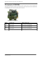
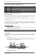
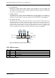
3.2.1 Interface and Power Supply Connector
Pin
Label
Description
1
GND
Module and signal ground
2
VCC
10… 30V DC power supply / nom. 24V DC
3
RS485A+
RS485 non-inverted bus signal
4
RS485B-
RS485 inverted bus signal
5
RS232_TxD
RS232 transmit data from module
6
RS232_RxD
RS232 receive data to module
Table 3.1 Connector for power supply and interfaces
3.2.1.1 Power Supply
When using supply voltages near the upper limit, a regulated power supply is mandatory. Please ensure,
that enough power filtering capacitors are available in the system (2200µF or more recommended) in
order to absorb mechanical energy fed back by the motor in stalling conditions.
The power supply should be designed in a way, that it supplies the nominal motor voltage at the
desired maximum motor power.
To ensure reliable operation of the unit, the power supply has to have a sufficient output capacitor and
the supply cables should have a low resistance, so that the chopper operation does not lead to an
increased power supply ripple directly at the unit. Power supply ripple due to the chopper operation
should be kept at a maximum of a few 100mV.
Guidelines for power supply:
- keep power supply cables as short as possible
- use large diameters for power supply cables
- add 2200µF or larger filter capacitors near the motor driver unit especially if the distance to the
power supply is large (i.e. more than 2-3m)
Note: there is no protection against reverse polarity integrated on the board.
3.2.1.2 RS485
For remote control and communication with a host system the PD-1161 provides a two wire RS485 bus
interface. For proper operation the following items should be taken into account when setting up an
RS485 network:
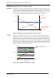
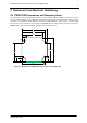
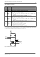
1. BUS STRUCTURE:
The network topology should follow a bus structure as closely as possible. That is, the
connection between each node and the bus itself should be as short as possible. Basically, it
should be short compared to the length of the bus.
c:>
node
1
node
n
- 1
node
n
Host
Slave Slave Slave
RS485
termination
resistor
(120 Ohm)
termination
resistor
(120 Ohm)
}
keep distance as
short as possible
Figure 3.5: RS485 bus structure