MODULE FOR STEPPER MOTORS MODULE Hardware Version V1.2 HARDWARE MANUAL + + TMCM-1021 Stepper Motor with Controller / Driver 0.7A RMS / 24V DC RS485 Interface + UNIQUE FEATURES: TRINAMIC Motion Control GmbH & Co. KG Hamburg, Germany www.trinamic.
TMCM-1021 V1.2 Hardware Manual (Ref. 1.00 / 2012-MAR-09) Table of Contents 1 2 3 Features........................................................................................................................................................................... 3 Order Codes ................................................................................................................................................................... 5 Mechanical and Electrical Interfacing ...............................
TMCM-1021 V1.2 Hardware Manual (Ref. 1.00 / 2012-MAR-09) 1 Features The TMCM-1021 is a single axis controller/driver module for 2-phase bipolar stepper motors with state of the art feature set. It is highly integrated, offers a convenient handling and can be used in many decentralized applications. The module can be mounted on the back of NEMA11 (28mm flange size) and has been designed for coil currents up to 0.7A RMS and 24V DC supply voltage.
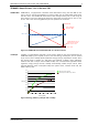
TMCM-1021 V1.2 Hardware Manual (Ref. 1.00 / 2012-MAR-09) 4 TRINAMICS UNIQUE FEATURES – EASY TO USE WITH TMCL stallGuard2™ stallGuard2 is a high-precision sensorless load measurement using the back EMF on the coils. It can be used for stall detection as well as other uses at loads below those which stall the motor. The stallGuard2 measurement value changes linearly over a wide range of load, velocity, and current settings. At maximum motor load, the value goes to zero or near to zero.
TMCM-1021 V1.2 Hardware Manual (Ref. 1.00 / 2012-MAR-09) 5 2 Order Codes Size of unit Description Single axis bipolar stepper motor controller/driver 28mm x 28mm electronics with integrated encoder electronics Order code TMCM-1021 Table 2.2: Order codes A cable loom set is available for this module: Order code TMCM-1021-CABLE Description Cable loom for TMCM-1021 1x cable loom for power, communication and (cable length approx. 200mm) 1x cable loom for motor connector (cable length ca. 200mm) Table 2.
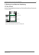
TMCM-1021 V1.2 Hardware Manual (Ref. 1.00 / 2012-MAR-09) 3 Mechanical and Electrical Interfacing 3.1 Size of Board The board with the controller/driver electronics has an overall size of 28mm x 28mm in order to fit on the back side of a NEMA11 (28mm flange size) stepper motor. The printed circuit board outline is marked green in the following figure: 28mm 27mm 25.5mm R 2mm PCB outline 25.5mm 27mm 28mm 28mm x 28mm Motor backbell R 1.3mm R 2.5mm Figure 3.
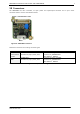
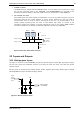
TMCM-1021 V1.2 Hardware Manual (Ref. 1.00 / 2012-MAR-09) 3.2 Connectors The TMCM-1021 has two connectors, an 8-pin power and input/output connector and a 4-pin motor connector (used to connect the attached motor). Power / Communication / IOs 1 1 Motor Figure 3.
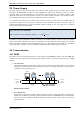
TMCM-1021 V1.2 Hardware Manual (Ref. 1.00 / 2012-MAR-09) 8 3.2.1 Power, Communication and I/O Connector An 8-pin JST PH-series 2mm pitch single row connector is used for power supply, RS485 serial communication and additional multi-purpose inputs and outputs. Pin 1 2 3 4 Label GND VDD RS485+ RS485- Direction Power (GND) Power (Supply) Bidirectional Bidirectional 5 IN_0 Input 6 IN_1 Input 7 OUT_0 / IN_2 Output / Input Description GND VDD (+9V…+28V) RS485 interface, diff.
TMCM-1021 V1.2 Hardware Manual (Ref. 1.00 / 2012-MAR-09) 9 3.3 Power Supply For proper operation care has to be taken with regard to power supply concept and design. Due to space restrictions the TMCM-1021 includes just about 20µF/35V of supply filter capacitors. These are ceramic capacitors which have been selected for high reliability and long life time. The module includes a 28V suppressor diode for over-voltage protection. There is no reverse polarity protection.
TMCM-1021 V1.2 Hardware Manual (Ref. 1.00 / 2012-MAR-09) 10 3. NUMBER OF NODES: The RS485 electrical interface standard (EIA-485) allows up to 32 nodes to be connected to a single bus. The bus transceiver used on the TMCM-1021 units (SN65HVD3082ED) has just 1/8th of the standard bus load and allows a maximum of 256 units to be connected to a single RS485 bus. 4.
TMCM-1021 V1.2 Hardware Manual (Ref. 1.00 / 2012-MAR-09) 11 The four inputs have alternate functionality depending on configuration in software.
TMCM-1021 V1.2 Hardware Manual (Ref. 1.00 / 2012-MAR-09) 12 4 Reset to Factory Defaults It is possible to reset the TMCM-1021 to factory default settings without establishing a communication link. This might be helpful in case communication parameters of the preferred interface have been set to unknown values or got accidentally lost. For this procedure two pads on the bottom side of the board have to be shortened (see Figure 4.1). Please perform the following steps: 1. 2. 3. 4. 5. 6. 7.
TMCM-1021 V1.2 Hardware Manual (Ref. 1.00 / 2012-MAR-09) 13 6 Operational Ratings The operational ratings show the intended or the characteristic ranges and should be used as design values.
TMCM-1021 V1.2 Hardware Manual (Ref. 1.00 / 2012-MAR-09) 14 7 Functional Description The TMCM-1021 is a highly integrated controller/driver module which can be controlled via RS485 interface. Communication traffic is kept low since all time critical operations (e.g. ramp calculations) are performed on board. The nominal supply voltage of the unit is 24V DC. The module is designed for both, standalone operation and direct mode. Full remote control of device with feedback is possible.
TMCM-1021 V1.2 Hardware Manual (Ref. 1.00 / 2012-MAR-09) 8 Life Support Policy TRINAMIC Motion Control GmbH & Co. KG does not authorize or warrant any of its products for use in life support systems, without the specific written consent of TRINAMIC Motion Control GmbH & Co. KG. Life support systems are equipment intended to support or sustain life, and whose failure to perform, when properly used in accordance with instructions provided, can be reasonably expected to result in personal injury or death.
TMCM-1021 V1.2 Hardware Manual (Ref. 1.00 / 2012-MAR-09) 9 Revision History 9.1 Document Revision Author Version Date 0.90 2011-AUG-02 GE 0.91 2011-AUG-25 SD 0.92 2011-NOV-10 GE 1.00 2012-MAR-09 SD GE – Göran Eggers SD – Sonja Dwersteg Description Initial version Information about left, right, and home switch added. Minor changes Motor connector corrected and motor connection added General purpose output circuit extended Hardware revision list updated Rule of thumb for capacitor added.