MODULE FOR STEPPER MOTORS MODULE Hardware Version V1.2 HARDWARE MANUAL + + TMCM-1140 1-Axis Stepper Controller / Driver 2 A / 24 V sensOstep™ Encoder USB, RS485, and CAN + UNIQUE FEATURES: TRINAMIC Motion Control GmbH & Co. KG Hamburg, Germany www.trinamic.
TMCM-1140 Hardware Manual (Rev. 1.01 / 2012-JUL-30) Table of Contents 1 2 3 Features........................................................................................................................................................................... 3 Order Codes ................................................................................................................................................................... 5 Mechanical and Electrical Interfacing ....................................
TMCM-1140 Hardware Manual (Rev. 1.01 / 2012-JUL-30) 3 1 Features The TMCM-1140 is a single axis controller/driver module for 2-phase bipolar stepper motors with state of the art feature set. It is highly integrated, offers a convenient handling and can be used in many decentralized applications. The module can be mounted on the back of NEMA 17 (42mm flange size) stepper motors and has been designed for coil currents up to 2 A RMS and 24 V DC supply voltage.
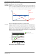
TMCM-1140 Hardware Manual (Rev. 1.01 / 2012-JUL-30) 4 TRINAMICS UNIQUE FEATURES – EASY TO USE WITH TMCL stallGuard2™ stallGuard2 is a high-precision sensorless load measurement using the back EMF on the coils. It can be used for stall detection as well as other uses at loads below those which stall the motor. The stallGuard2 measurement value changes linearly over a wide range of load, velocity, and current settings. At maximum motor load, the value goes to zero or near to zero.
TMCM-1140 Hardware Manual (Rev. 1.01 / 2012-JUL-30) 5 2 Order Codes Order code TMCM-1140-option Size (mm3) Description Single axis bipolar stepper motor controller / driver electronics with 37 x 37 x 11.5 integrated sensOstep encoder and coolStep feature Table 2.1 Order codes The following options are available: Firmware option -TMCL Description Module pre-programmed with TMCL firmware Order code example: TMCM-1140-TMCL Table 2.
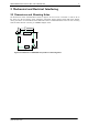
TMCM-1140 Hardware Manual (Rev. 1.01 / 2012-JUL-30) 6 3 Mechanical and Electrical Interfacing 3.1 Dimensions and Mounting Holes The dimensions of the controller/driver board are approx. 37 mm x 37 mm x 11.5 mm in order to fit on the back of a 42 mm stepper motor. Maximum component height (height above PCB level) without mating connectors is around 8mm above PCB level and 2 mm below PCB level. There are two mounting holes for M3 screws for mounting to a NEMA17 stepper motor.
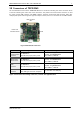
TMCM-1140 Hardware Manual (Rev. 1.01 / 2012-JUL-30) 7 3.2 Connectors of TMCM-1140 The controller/driver board of the TMCM-1140 offers four connectors including the motor connector which is used for attaching the motor coils to the electronics. The power and communication connector is used for power supply, CAN interface, and RS485 interface. The 8pin multipurpose I/O connector offers four multipurpose inputs and two general purpose outputs. Further, there is a connector for the USB interface.
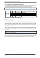
TMCM-1140 Hardware Manual (Rev. 1.01 / 2012-JUL-30) 8 3.2.1 Power and Communication Connector A 6pin JST PH-series 2mm pitch single row connector is used for power supply, RS485 and CAN serial communication. Please mention the additional power supply information in chapter 3.2.1.1. Note: CAN interface will be de-activated in case USB is connected due to internal sharing of hardware resources.
TMCM-1140 Hardware Manual (Rev. 1.01 / 2012-JUL-30) 9 3.2.1.2 RS485 For remote control and communication with a host system the TMCM-1140 provides a two wire RS485 bus interface. For proper operation the following items should be taken into account when setting up an RS485 network: 1. BUS STRUCTURE: The network topology should follow a bus structure as closely as possible. That is, the connection between each node and the bus itself should be as short as possible.
TMCM-1140 Hardware Manual (Rev. 1.01 / 2012-JUL-30) 10 3.2.1.3 CAN For remote control and communication with a host system the TMCM-1140 provides a CAN bus interface. Please note that the CAN interface is not available in case USB is connected. For proper operation the following items should be taken into account when setting up a CAN network: 1. BUS STRUCTURE: The network topology should follow a bus structure as closely as possible.
TMCM-1140 Hardware Manual (Rev. 1.01 / 2012-JUL-30) 11 3.2.2 Multipurpose I/O Connector An 8pin JST PH-series 2mm pitch single row connector is available for all multipurpose inputs and outputs.
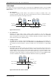
TMCM-1140 Hardware Manual (Rev. 1.01 / 2012-JUL-30) 12 3.2.2.1 Digital Inputs IN_0, IN_1, IN_2 The eight pin connector of the TMCM-1140 provides three multipurpose digital inputs IN_0, IN_1 and IN_2. All three inputs accept up to +24V input signals. They are protected against these higher voltages using voltage resistor dividers together with limiting diodes against voltages below 0V (GND) and above +3.3V DC (see figure below). common switch for all three digital inputs +5V 2k2 +3.
TMCM-1140 Hardware Manual (Rev. 1.01 / 2012-JUL-30) 13 All three digital inputs are connected to the on-board processor and can be used as general purpose digital inputs (default). 3.2.2.2 Analog Input AIN_0 The eight pin connector of the TMCM-1140 provides one dedicated analog input AIN_0. This dedicated analog input offers a full scale input range of 0… +10 V with a resolution of the internal analog-to-digital converter of the microcontroller of 12bit (0… 4095).
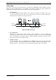
TMCM-1140 Hardware Manual (Rev. 1.01 / 2012-JUL-30) 14 In contrast OUT_0 is able to supply +5V (100mA max.) to an external load. An integrated P-channel MOSFET allows to switch on / off this +5V supply in software (see figure below). This output might be used in order to supply +5V to an external encoder circuit. +5V microcontroller OUT_0 10k 100pF GND GND Figure 3.10 General purpose output OUT_0 www.trinamic.
TMCM-1140 Hardware Manual (Rev. 1.01 / 2012-JUL-30) 15 3.2.3 Motor Connector As motor connector a 4pin JST PH-series 2mm pitch single row connector is available. The motor connector is used for connecting the four motor wires of the two motor coils of the bipolar stepper motor to the electronics. 1 4 Pin 1 2 3 4 Label OB2 OB1 OA2 OA1 Direction Output Output Output Output Pin Pin Pin Pin 2 1 2 1 of of of of motor motor motor motor Description coil B coil B coil A coil A Table 3.
TMCM-1140 Hardware Manual (Rev. 1.01 / 2012-JUL-30) 16 3.2.4 Mini-USB Connector A 5pin mini-USB connector is available on-board for serial communication (as alternative to the CAN and RS485 interface). This module supports USB 2.0 Full-Speed (12Mbit/s) connections. CAN interface will be de-activated as soon as USB is connected due to internal sharing of hardware resources.
TMCM-1140 Hardware Manual (Rev. 1.01 / 2012-JUL-30) 17 4 Reset to Factory Defaults It is possible to reset the TMCM-1140 to factory default settings without establishing a communication link. This might be helpful in case communication parameters of the preferred interface have been set to unknown values or got accidentally lost. For this procedure two pads on the bottom side of the board have to be shortened. Please perform the following steps: 1. 2. 3. 4. 5. 6. 7.
TMCM-1140 Hardware Manual (Rev. 1.01 / 2012-JUL-30) 18 5 On-Board LEDs The board offers two LEDs in order to indicate board status. The function of both LEDs is dependent on the firmware version. With standard TMCL firmware the green LED should be flashing slowly during operation and the red LED should be off. When there is no valid firmware programmed into the board or during firmware update the red and green LEDs are permanently on.
TMCM-1140 Hardware Manual (Rev. 1.01 / 2012-JUL-30) 19 6 Operational Ratings The operational ratings show the intended or the characteristic ranges and should be used as design values.
TMCM-1140 Hardware Manual (Rev. 1.01 / 2012-JUL-30) 20 7 Functional Description The TMCM-1140 is a highly integrated controller/driver module which can be controlled via several serial interfaces. Communication traffic is kept low since all time critical operations (e.g. ramp calculations) are performed on board. The nominal supply voltage of the unit is 24V DC. The module is designed for both, standalone operation and direct mode. Full remote control of device with feedback is possible.
TMCM-1140 Hardware Manual (Rev. 1.01 / 2012-JUL-30) 21 8 TMCM-1140 Operational Description 8.1 Calculation: Velocity and Acceleration vs. Microstep and Fullstep Frequency The values of the parameters sent to the TMC429 do not have typical motor values like rotations per second as velocity. But these values can be calculated from the TMC429 parameters as shown in this section. PARAMETERS OF TMC429 Signal Description fCLK clock-frequency velocity a_max maximum acceleration divider for the velocity.
TMCM-1140 Hardware Manual (Rev. 1.01 / 2012-JUL-30) EXAMPLE: Signal f_CLK velocity a_max pulse_div ramp_div usrs msf 16 MHz 1000 122070.31 Hz 21 2048 32 122070.31 fsf [ Hz ] a value 16 MHz 1000 1000 1 1 6 26 (16Mhz ) 2 1000 11 29 2 1907.34 Hz 119.21 MHz s MHz s 1.863 MHz 6 s 2 119.21 af CALCULATION OF THE NUMBER OF ROTATIONS A stepper motor has e.g. 72 fullsteps per rotation. RPS RPM fsf 1907.34 26.49 fullsteps per rotation 72 fsf 60 1907.
TMCM-1140 Hardware Manual (Rev. 1.01 / 2012-JUL-30) 9 Life Support Policy TRINAMIC Motion Control GmbH & Co. KG does not authorize or warrant any of its products for use in life support systems, without the specific written consent of TRINAMIC Motion Control GmbH & Co. KG. Life support systems are equipment intended to support or sustain life, and whose failure to perform, when properly used in accordance with instructions provided, can be reasonably expected to result in personal injury or death.
TMCM-1140 Hardware Manual (Rev. 1.01 / 2012-JUL-30) 24 10 Revision History 10.1 Document Revision Version Date Author Description GE - Göran Eggers SD - Sonja Dwersteg 0.90 0.91 2011-DEC-22 2012-MAY-02 GE GE 1.00 2012-JUN-12 SD 1.01 2012-JUL-30 SD Initial version Updated for TMCM-1140_V11 pcb version First complete version including new chapters about: reset to factory defaults, and LEDs Internal circuit of inputs corrected. Table 10.1 Document revision 10.