MODULE FOR STEPPER MOTORS MODULE Hardware Version V1.1 HARDWARE MANUAL + + TMCM-1160 1-Axis Stepper Controller / Driver 2.8 A / 48 V USB, RS485, and CAN Step/Dir Interface sensOstep™ Encoder + UNIQUE FEATURES: TRINAMIC Motion Control GmbH & Co. KG Hamburg, Germany www.trinamic.
TMCM-1160 V1.01 Hardware Manual (Rev. 1.01 / 2012-JUL-27) Table of Contents 1 2 3 Features........................................................................................................................................................................... 3 Order Codes ................................................................................................................................................................... 5 Mechanical and Electrical Interfacing ..............................
TMCM-1160 V1.01 Hardware Manual (Rev. 1.01 / 2012-JUL-27) 3 1 Features The TMCM-1160 is a single axis controller/driver module for 2-phase bipolar stepper motors with state of the art feature set. It is highly integrated, offers a convenient handling and can be used in many decentralized applications. The module can be mounted on the back of NEMA 23 (57mm flange size) or NEMA 24 (60mm flange size) stepper motors and has been designed for coil currents up to 2.8 A RMS and 12, 24 or 48 V DC supply voltage.
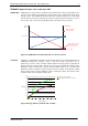
TMCM-1160 V1.01 Hardware Manual (Rev. 1.01 / 2012-JUL-27) 4 TRINAMICS UNIQUE FEATURES – EASY TO USE WITH TMCL stallGuard2™ stallGuard2 is a high-precision sensorless load measurement using the back EMF on the coils. It can be used for stall detection as well as other uses at loads below those which stall the motor. The stallGuard2 measurement value changes linearly over a wide range of load, velocity, and current settings. At maximum motor load, the value goes to zero or near to zero.
TMCM-1160 V1.01 Hardware Manual (Rev. 1.01 / 2012-JUL-27) 2 5 Order Codes Order code TMCM-1160-option Size (mm3) Description Single axis bipolar stepper motor controller / driver 60 x 60 x 15 electronics with integrated sensOstep encoder and coolStep feature Table 2.1 Order codes The following options are available: Firmware option -TMCL Description Module pre-programmed with TMCL firmware Order code example TMCM-1160-TMCL Table 2.
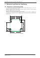
TMCM-1160 V1.01 Hardware Manual (Rev. 1.01 / 2012-JUL-27) 3 6 Mechanical and Electrical Interfacing 3.1 Dimensions and Mounting Holes - The dimensions of the TMCM-1160 controller/driver board are approx. 60 mm x 60 mm in order to fit on the back side of the 60 mm stepper motor. Maximum component height above PCB level without mating connectors is around 10.5 mm (jumpers for RS485 / CAN termination included). Maximum component height below PCB level is around 4 mm.
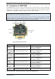
TMCM-1160 V1.01 Hardware Manual (Rev. 1.01 / 2012-JUL-27) 7 3.2 Connectors of TMCM-1160 The TMCM-1160 offers seven connectors including the motor connector which is used for attaching the motor coils to the electronics. In addition to the power connector there are two connectors for serial communication (mini-USB connector and 5pin connector for RS485 and CAN) and three connectors for Step/Direction, multipurpose input/output signals, and for an external encoder.
TMCM-1160 V1.01 Hardware Manual (Rev. 1.01 / 2012-JUL-27) 8 3.2.1 Power Connector This module offers separate power supply inputs for digital logic (connector pin 2) and driver/power stage (connector pin 1). Both supply inputs use common ground connections (connector pin 4). This way, power supply for the driver stage may be switched off while still maintaining position and status information when keeping digital logic supply active.
TMCM-1160 V1.01 Hardware Manual (Rev. 1.01 / 2012-JUL-27) 9 GUIDELINES FOR POWER SUPPLY: - keep power supply cables as short as possible use large diameters for power supply cables add 2200µF or larger filter capacitors near the motor driver unit especially if the distance to the power supply is large (i.e. more than 2-3m) 3.2.2 Serial Communication Connector The module supports RS485 and CAN communication via this connector.
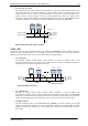
TMCM-1160 V1.01 Hardware Manual (Rev. 1.01 / 2012-JUL-27) 4. 10 NO FLOATING BUS LINES: Avoid floating bus lines while neither the host/master nor one of the slaves along the bus line is transmitting data (all bus nodes switched to receive mode). Floating bus lines may lead to communication errors. In order to ensure valid signals on the bus it is recommended to use a resistor network connecting both bus lines to well defined logic levels.
TMCM-1160 V1.01 Hardware Manual (Rev. 1.01 / 2012-JUL-27) 11 3.2.3 Multipurpose I/O Connector A 2mm pitch 8-pin JST B8B-PH-K connector is used for connecting general purpose inputs, home and stop switches and outputs to the unit: Pin Label 1 OUT_0 2 OUT_1 3 IN_0 4 IN_1 5 STOP_L 6 STOP_R 7 HOME 8 GND 1 8 Description General purpose output, open drain (max. 1A) Integrated freewheeling diode connected to +VLogic General purpose output, open drain (max.
TMCM-1160 V1.01 Hardware Manual (Rev. 1.01 / 2012-JUL-27) 12 All three digital inputs are connected to the on-board processor and can be used as general purpose digital inputs! 3.2.3.2 General Purpose Inputs IN_0 and IN_1 The eight pin connector of the TMCM-1160 provides two general purpose inputs which may be used as either digital or analog inputs.
TMCM-1160 V1.01 Hardware Manual (Rev. 1.01 / 2012-JUL-27) 13 3.2.4 Step/Direction Connector A 2mm pitch 4-pin JST B4B-PH-K connector is used for step and direction input signals. This is an option in case the on-board controller is used for configuration of the driver stage, only. The Step/Direction input is optically isolated and will allow direct control of the driver stage.
TMCM-1160 V1.01 Hardware Manual (Rev. 1.01 / 2012-JUL-27) 14 3.2.5 Encoder Connector The module supports an external incremental a/b/n encoder via this connector. The external encoder may be used in addition or as an alternative to the internal / on-board sensOstep encoder.
TMCM-1160 V1.01 Hardware Manual (Rev. 1.01 / 2012-JUL-27) 3.2.6 15 Motor Connector Both motor coil windings (bipolar stepper motor) are connected to the motor connector. 1 4 Pin 1 2 3 4 Label OA1 OA2 OB1 OB2 Description Motor coil A Motor coil A Motor coil B Motor coil B Figure 3.3 Motor connector www.trinamic.
TMCM-1160 V1.01 Hardware Manual (Rev. 1.01 / 2012-JUL-27) 16 3.2.7 Mini-USB Connector A 5-pin standard mini-USB connector is available on board. This module supports USB 2.0 full-speed (12Mbit/s) connections. Please note: On-board digital core logic (mainly processor and EEPROM) will be powered via USB in case no other supply is connected.
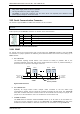
TMCM-1160 V1.01 Hardware Manual (Rev. 1.01 / 2012-JUL-27) 4 17 Jumpers Most settings of the board are done through the software. Nevertheless, two jumpers are available for configuration. CAN bus termination RS485 bus termination Figure 4.1 RS485 and CAN bus termination 4.1 RS485 Bus Termination The board includes a 120 Ohm resistor for proper bus termination of the RS485 interface. When this jumper is closed, the resistor will be placed between the two differential bus lines RS485+ and RS485-. 4.
TMCM-1160 V1.01 Hardware Manual (Rev. 1.01 / 2012-JUL-27) 5 18 Reset to Factory Defaults It is possible to reset the PD-1160 to factory default settings without establishing a communication link. This might be helpful in case communication parameters of the preferred interface have been set to unknown values or got accidentally lost. For this procedure two pads on the bottom side of the board have to be shortened (see Figure 5.1). Short these two pads. PERFORM THE FOLLOWING STEPS: 1. 2. 3. 4. 5. 6. 7.
TMCM-1160 V1.01 Hardware Manual (Rev. 1.01 / 2012-JUL-27) 6 19 On-board LED The board offers two LEDs in order to indicate board status. The function of both LEDs is dependent on the firmware version. With standard TMCL firmware the green LED should be flashing during operation and the red LED should be off. When there is no valid firmware programmed into the board or during firmware update the red and green LEDs are permanently on.
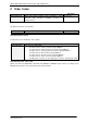
TMCM-1160 V1.01 Hardware Manual (Rev. 1.01 / 2012-JUL-27) 7 20 Operational Ratings The operational ratings show the intended or the characteristic ranges and should be used as design values.
TMCM-1160 V1.01 Hardware Manual (Rev. 1.
TMCM-1160 V1.01 Hardware Manual (Rev. 1.01 / 2012-JUL-27) 8 22 Functional Description The TMCM-1160 is a highly integrated controller/driver module which can be controlled via several serial interfaces. Communication traffic is kept low since all time critical operations (e.g. ramp calculations) are performed on board. Common supply voltages are +12VDC / +24VDC / +48VDC. The module is designed for both, standalone operation and direct mode. Full remote control of device with feedback is possible.
TMCM-1160 V1.01 Hardware Manual (Rev. 1.01 / 2012-JUL-27) 9 23 TMCM-1160 Operational Description 9.1 Calculation: Velocity and Acceleration vs. Microstep and Fullstep Frequency The values of the parameters sent to the TMC429 do not have typical motor values like rotations per second as velocity. But these values can be calculated from the TMC429 parameters as shown in this section.
TMCM-1160 V1.01 Hardware Manual (Rev. 1.01 / 2012-JUL-27) EXAMPLE: Signal f_CLK velocity a_max pulse_div ramp_div usrs msf 16 MHz 1000 122070.31 Hz 21 2048 32 122070.31 fsf [ Hz ] a value 16 MHz 1000 1000 1 1 6 26 (16Mhz ) 2 1000 11 29 2 1907.34 Hz 119.21 MHz s MHz s 1.863 MHz 6 s 2 119.21 af CALCULATION OF THE NUMBER OF ROTATIONS A stepper motor has e.g. 72 fullsteps per rotation. RPS RPM fsf 1907.34 26.49 fullsteps per rotation 72 fsf 60 1907.
TMCM-1160 V1.01 Hardware Manual (Rev. 1.01 / 2012-JUL-27) 10 Life Support Policy TRINAMIC Motion Control GmbH & Co. KG does not authorize or warrant any of its products for use in life support systems, without the specific written consent of TRINAMIC Motion Control GmbH & Co. KG. Life support systems are equipment intended to support or sustain life, and whose failure to perform, when properly used in accordance with instructions provided, can be reasonably expected to result in personal injury or death.
TMCM-1160 V1.01 Hardware Manual (Rev. 1.01 / 2012-JUL-27) 26 11 Revision History 11.1 Document Revision Version Date Author Description GE - Göran Eggers SD - Sonja Dwersteg 0.91 2012-MAY-03 GE 1.00 2012-JUN-13 SD 1.01 2012-JUL-27 SD Initial version First complete version including the following chapters: Reset to factory defaults, LEDs Figure 3.6 (general purpose inputs) corrected. Table 11.1 Document revision 11.