
User manual

TMCM-1180 and PD86-1180 TMCL Firmware V4.42 Manual (Rev. 1.08 / 2012-NOV-20) 12
www.trinamic.com
5 TMCL™ and TMCL-IDE
The TMCM-1180 supports TMCL™ direct mode (binary commands or ASCII interface) and standalone TMCL™
program execution. You can store up to 2048 TMCL™ instructions on it.
In direct mode and most cases the TMCL™ communication over RS485, RS232, USB or CAN follows a strict
master/slave relationship. That is, a host computer (e.g. PC/PLC) acting as the interface bus master will send a
command to the TMCL-1180. The TMCL™ interpreter on the module will then interpret this command, do the
initialization of the motion controller, read inputs and write outputs or whatever is necessary according to the
specified command. As soon as this step has been done, the module will send a reply back over
RS485/RS232/USB/CAN to the bus master. Only then should the master transfer the next command. Normally,
the module will just switch to transmission and occupy the bus for a reply, otherwise it will stay in receive
mode. It will not send any data over the interface without receiving a command first. This way, any collision
on the bus will be avoided when there are more than two nodes connected to a single bus.
The Trinamic Motion Control Language [TMCL™] provides a set of structured motion control commands. Every
motion control command can be given by a host computer or can be stored in an EEPROM on the TMCM
module to form programs that run standalone on the module. For this purpose there are not only motion
control commands but also commands to control the program structure (like conditional jumps, compare and
calculating).
Every command has a binary representation and a mnemonic. The binary format is used to send commands
from the host to a module in direct mode, whereas the mnemonic format is used for easy usage of the
commands when developing standalone TMCL™ applications using the TMCL-IDE (IDE means Integrated
Development Environment).
There is also a set of configuration variables for the axis and for global parameters which allow individual
configuration of nearly every function of a module. This manual gives a detailed description of all TMCL™
commands and their usage.
5.1 Binary command format
Every command has a mnemonic and a binary representation. When commands are sent from a host to a
module, the binary format has to be used. Every command consists of a one-byte command field, a one-byte
type field, a one-byte motor/bank field and a four-byte value field. So the binary representation of a command
always has seven bytes. When a command is to be sent via RS232, RS485 or USB interface, it has to be
enclosed by an address byte at the beginning and a checksum byte at the end. In this case it consists of nine
bytes.
This is different when communicating is via the CAN bus. Address and checksum are included in the CAN
standard and do not have to be supplied by the user.
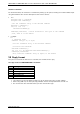
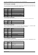
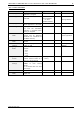
The binary command format for RS232/RS485/USB is as follows:
Bytes
Meaning
1
Module address
1
Command number
1
Type number
1
Motor or Bank number
4
Value (MSB first!)
1
Checksum
The checksum is calculated by adding up all the other bytes using an 8-bit addition.
When using CAN bus, just leave out the first byte (module address) and the last byte (checksum).