
User manual


TMCM-1640 TMCL Firmware V2.00 Manual (Rev. 2.00 / 2012-JUL-31) 51
www.trinamic.com
7.3 Velocity Regulation
Based on the current regulation the motor velocity can be controlled by the velocity PID regulator.
TIMING CONTROL VALUE
Also, the velocity PID regulator uses a timing control value (PID regulation loop delay, axis parameter 133)
which determines how often the PID regulator is invoked. It is given in multiple of 1ms:
= resulting delay between two PID calculations
= PID regulation loop delay parameter
For most applications it is recommended to leave this parameter unchanged at its default value of 1ms.
Higher values may be necessary for very slow and less dynamic drives.
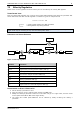
STRUCTURE OF THE VELOCITY REGULATOR
v
ACTUAL
v
RAMPGEN
I
PARAM
/ 65536
P
PARAM
/ 256
Clip
I
CLIP
e
SUM
Clip
I
Max
I
TARGET
Clip
V
Max
Figure 7.3: Velocity regulation
Parameter
Description
v
ACTUAL
Actual motor velocity (GAP 3)
v
RAMPGEN
Target velocity of ramp generator (SAP 2, GAP 13)
v
Max
Max. target velocity (SAP 4)
e
SUM
Error sum for integral calculation (GAP 229)
P
PARAM
Velocity P parameter (SAP 234)
I
PARAM
Velocity I parameter (SAP 235)
I
Max
Max. target current (SAP 6)
I
Target
Target current for current PID regulator (GAP 155)
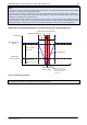
PARAMETERIZING THE VELOCITY REGULATOR SET
1. Set the velocity I parameter to zero.
2. Start the motor by using a medium target velocity (e.g. 2000 rpm).
3. Modify the velocity P parameter. Start from a low value and go to a higher value, until the actual
motor speed reaches 80 or 90% of the target velocity.
4. The lasting 10 or 20% speed difference can be reduced by slowly increasing the velocity I
parameter.