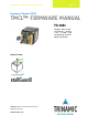
MECHATRONIC DRIVE WITH STEPPER MOTOR PANdrive Firmware Version V1.19 TMCL™ FIRMWARE MANUAL + + PD-1021 Stepper Motor with Controller / Driver 0.06 - 0.12Nm / 24V sensOstep™ Encoder RS485 Interface + UNIQUE FEATURES: TRINAMIC Motion Control GmbH & Co. KG Hamburg, Germany www.trinamic.
PD-1021 TMCL Firmware V1.19 Manual (Rev. 1.01 / 2012-JUL-30) Table of Contents 1 2 Features........................................................................................................................................................................... 4 Putting the PANdrive into Operation ..................................................................................................................... 6 2.1 Basic Set-Up ........................................................................
PD-1021 TMCL Firmware V1.19 Manual (Rev. 1.01 / 2012-JUL-30) 4.1 Velocity Calculation ........................................................................................................................................... 64 4.2 stallGuard2 ........................................................................................................................................................... 65 4.3 coolStep Related Axis Parameters .......................................................................
PD-1021 TMCL Firmware V1.19 Manual (Rev. 1.01 / 2012-JUL-30) 4 1 Features The PANdrive™ PD-1021 is a full mechatronic solution with state of the art feature set. It is highly integrated and offers a convenient handling. The PD-1021 includes a stepper motor, controller/driver electronics, and TRINAMICs sensOstep™ encoder. It can be used in many decentralized applications and has been designed for 0.06… 0.12 Nm max. holding torque and 24V DC nominal supply voltage.
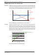
PD-1021 TMCL Firmware V1.19 Manual (Rev. 1.01 / 2012-JUL-30) 5 TRINAMICS UNIQUE FEATURES – EASY TO USE WITH TMCL stallGuard2™ stallGuard2 is a high-precision sensorless load measurement using the back EMF on the coils. It can be used for stall detection as well as other uses at loads below those which stall the motor. The stallGuard2 measurement value changes linearly over a wide range of load, velocity, and current settings. At maximum motor load, the value goes to zero or near to zero.
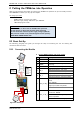
PD-1021 TMCL Firmware V1.19 Manual (Rev. 1.01 / 2012-JUL-30) 6 2 Putting the PANdrive into Operation Here you can find basic information for putting your PD-1021 into operation. If you are already common with TRINAMICs modules you may skip this chapter.
PD-1021 TMCL Firmware V1.19 Manual (Rev. 1.01 / 2012-JUL-30) 2. Switch ON the power supply Turn power ON. The green LED for power lights up and the motor is powered but in standstill now. If this does not occur, switch power OFF and check your connections as well as the power supply. 2.1.2 Start the TMCL-IDE Software Development Environment The TMCL-IDE is available on www.trinamic.com. Installing the TMCL-IDE: Make sure the COM port you intend to use is not blocked by another program.
PD-1021 TMCL Firmware V1.19 Manual (Rev. 1.01 / 2012-JUL-30) 8 2.2 Using TMCL Direct Mode 1. Start TMCL Direct Mode. Direct Mode 2. If the communication is established the PD-1021 is automatically detected. If the module is not detected, please check all points above (cables, interface, power supply, COM port, baud rate). 3. Issue a command by choosing Instruction, Type (if necessary), Motor, and Value and click Execute to send it to the module.
PD-1021 TMCL Firmware V1.19 Manual (Rev. 1.01 / 2012-JUL-30) 2.2.1 9 Important Motor Settings There are some axis parameters which have to be adjusted right in the beginning after installing your module. Please set the upper limiting values for the speed (axis parameter 4), the acceleration (axis parameter 5), and the current (axis parameter 6). Further set the standby current (axis parameter 7) and choose your microstep resolution with axis parameter 140.
PD-1021 TMCL Firmware V1.19 Manual (Rev. 1.01 / 2012-JUL-30) 2.3 Testing with a Simple TMCL Program Type in the following program: Loop: ROL 0, 50000 WAIT TICKS, 0, 500 MST 0 ROR 0, 50000 WAIT TICKS, 0, 500 MST 0 //Rotate motor 0 with speed 50000 SAP 4, 0, 50000 SAP 5, 0, 50000 MVP ABS, 0, 100000 WAIT POS, 0, 0 MVP ABS, 0, -100000 WAIT POS, 0, 0 JA Loop //Set max. Velocity //Set max.
PD-1021 TMCL Firmware V1.19 Manual (Rev. 1.01 / 2012-JUL-30) 11 3 TMCL and the TMCL-IDE: Introduction As with most TRINAMIC modules the software running on the microprocessor of the PD-1061 consists of two parts, a boot loader and the firmware itself. Whereas the boot loader is installed during production and testing at TRINAMIC and remains untouched throughout the whole lifetime, the firmware can be updated by the user. New versions can be downloaded free of charge from the TRINAMIC website (http://www.
PD-1021 TMCL Firmware V1.19 Manual (Rev. 1.01 / 2012-JUL-30) 12 Checksum calculation As mentioned above, the checksum is calculated by adding up all bytes (including the module address byte) using 8-bit addition.
PD-1021 TMCL Firmware V1.19 Manual (Rev. 1.01 / 2012-JUL-30) 3.2.1 13 Status Codes The reply contains a status code. The status code can have one of the following values: Code 100 101 Meaning Successfully executed, no error Command loaded into TMCL program EEPROM Wrong checksum Invalid command Wrong type Invalid value Configuration EEPROM locked Command not available 1 2 3 4 5 6 3.3 Standalone Applications The module is equipped with an EEPROM for storing TMCL applications.
PD-1021 TMCL Firmware V1.19 Manual (Rev. 1.01 / 2012-JUL-30) Command RFS SIO Number 13 14 GIO CALC COMP JC JA CSUB RSUB EI DI WAIT STOP SCO 15 19 20 21 22 23 24 25 26 27 28 30 GCO CCO CALCX AAP AGP VECT RETI ACO 31 32 33 34 35 37 38 39 3.4.
PD-1021 TMCL Firmware V1.19 Manual (Rev. 1.01 / 2012-JUL-30) Mnemonic SAP GAP STGP RSGP Command number 5 6 11 12 15 Meaning Set axis parameter Get axis parameter Store global parameters Restore global parameters 3.4.2.3 Control Commands These commands are used to control the program flow (loops, conditions, jumps etc.). It does not make sense to use them in direct mode. They are intended for standalone mode only.
PD-1021 TMCL Firmware V1.19 Manual (Rev. 1.01 / 2012-JUL-30) Mnemonic EI DI VECT RETI 3.4.2.6.1 Command number 25 26 37 38 16 Meaning Enable interrupt Disable interrupt Set interrupt vector Return from interrupt Interrupt Types There are many different interrupts in TMCL, like timer interrupts, stop switch interrupts, position reached interrupts, and input pin change interrupts. Each of these interrupts has its own interrupt vector. Each interrupt vector is identified by its interrupt number.
PD-1021 TMCL Firmware V1.19 Manual (Rev. 1.
PD-1021 TMCL Firmware V1.19 Manual (Rev. 1.01 / 2012-JUL-30) 18 3.5 Commands The module specific commands are explained in more detail on the following pages. They are listed according to their command number. 3.5.1 ROR (rotate right) With this command the motor will be instructed to rotate with a specified velocity in positive direction (increasing the position counter). Like on all other TMCL modules, the motor will be accelerated or decelerated to the speed given with the command.
PD-1021 TMCL Firmware V1.19 Manual (Rev. 1.01 / 2012-JUL-30) 3.5.2 19 ROL (rotate left) With this command the motor will be instructed to rotate with a specified velocity (opposite direction compared to ROR, decreasing the position counter). Like on all other TMCL modules, the motor will be accelerated or decelerated to the speed given with the command. The speed is given in microsteps per second (pps). For conversion of this value into rounds per minute etc. please refer to chapter 5.2, also.
PD-1021 TMCL Firmware V1.19 Manual (Rev. 1.01 / 2012-JUL-30) 3.5.3 20 MST (motor stop) With this command the motor will be instructed to stop. The command uses the normal acceleration parameter (soft stop / deceleration ramp possible). Internal function: The axis parameter target velocity is set to zero. Related commands: ROL, ROR, SAP, GAP Mnemonic: MST 0 Binary representation: INSTRUCTION NO.
PD-1021 TMCL Firmware V1.19 Manual (Rev. 1.01 / 2012-JUL-30) 3.5.4 21 MVP (move to position) With this command the motor will be instructed to move to a specified relative or absolute position or a pre-programmed coordinate. It will use the acceleration/deceleration ramp and the positioning speed programmed into the unit. This command is non-blocking – that is, a reply will be sent immediately after command interpretation and initialization of the motion controller.
PD-1021 TMCL Firmware V1.19 Manual (Rev. 1.
PD-1021 TMCL Firmware V1.19 Manual (Rev. 1.01 / 2012-JUL-30) 3.5.5 23 SAP (set axis parameter) With this command most of the motion control parameters of the module can be specified. The settings will be stored in SRAM and therefore, will be volatile. That is, information will be lost after power off. Please use command STAP (store axis parameter) in order to store any setting permanently. Internal function: The parameter format is converted ignoring leading zeros (or ones for negative values).
PD-1021 TMCL Firmware V1.19 Manual (Rev. 1.01 / 2012-JUL-30) 3.5.6 24 GAP (get axis parameter) Most parameters of the PD-1021 can be adjusted individually for the axis. With this parameter they can be read out. In standalone mode the requested value is also transferred to the accumulator register for further processing purposes (such as conditioned jumps). In direct mode the value read is only output in the value field of the reply (without affecting the accumulator).
PD-1021 TMCL Firmware V1.19 Manual (Rev. 1.01 / 2012-JUL-30) 3.5.7 25 STAP (store axis parameter) An axis parameter previously set with a Set Axis Parameter command (SAP) will be stored permanent. Most parameters are automatically restored after power up. Internal function: An axis parameter value stored in SRAM will be transferred to EEPROM and loaded from EEPORM after next power up. Related commands: SAP, RSAP, GAP, AAP Mnemonic: STAP , 0 Binary representation: INSTRUCTION NO.
PD-1021 TMCL Firmware V1.19 Manual (Rev. 1.01 / 2012-JUL-30) 3.5.8 26 RSAP (restore axis parameter) For all configuration-related axis parameters non-volatile memory locations are provided. By default, most parameters are automatically restored after power up. A single parameter that has been changed before can be reset by this instruction also. Internal function: The specified parameter is copied from the configuration EEPROM memory to its RAM location.
PD-1021 TMCL Firmware V1.19 Manual (Rev. 1.01 / 2012-JUL-30) 3.5.9 27 SGP (set global parameter) With this command most of the module specific parameters not directly related to motion control can be specified and the TMCL user variables can be changed. Global parameters are related to the host interface, peripherals or application specific variables. The different groups of these parameters are organized in banks to allow a larger total number for future products.
PD-1021 TMCL Firmware V1.19 Manual (Rev. 1.01 / 2012-JUL-30) 28 3.5.10 GGP (get global parameter) All global parameters can be read with this function. Global parameters are related to the host interface, peripherals or application specific variables. The different groups of these parameters are organized in banks to allow a larger total number for future products. Currently, only bank 0 and 1 are used for global parameters, and bank 2 is used for user variables.
PD-1021 TMCL Firmware V1.19 Manual (Rev. 1.01 / 2012-JUL-30) 29 3.5.11 STGP (store global parameter) This command is used to store TMCL user variables permanently in the EEPROM of the module. Some global parameters are located in RAM memory, so without storing them any modification will be lost at power down. This instruction enables permanent storing. Most parameters are automatically restored after power up.
PD-1021 TMCL Firmware V1.19 Manual (Rev. 1.01 / 2012-JUL-30) 30 3.5.12 RSGP (restore global parameter) With this command the contents of a TMCL user variable can be restored from the EEPROM. By default, most parameters are automatically restored after power up. A single parameter that has been changed before can be reset by this instruction. Internal function: the specified parameter is copied from the configuration EEPROM memory to its RAM location.
PD-1021 TMCL Firmware V1.19 Manual (Rev. 1.01 / 2012-JUL-30) 31 3.5.13 RFS (reference search) The TMCL firmware has a built-in reference search algorithm which can be used. The reference search algorithm provides switching point calibration and three switch modes. The status of the reference search can also be queried to see if it has already finished. Please see the appropriate parameters in the axis parameter table to configure the reference search algorithm to meet your needs (chapter 4).
PD-1021 TMCL Firmware V1.19 Manual (Rev. 1.01 / 2012-JUL-30) 32 3.5.14 SIO (set output) This command sets the status of the general digital output either to low (0) or to high (1). Internal function: the passed value is transferred to the specified output line. Related commands: GIO, WAIT Mnemonic: SIO , , Binary representation: INSTRUCTION NO.
PD-1021 TMCL Firmware V1.19 Manual (Rev. 1.01 / 2012-JUL-30) 33 Available I/O ports of PD-1021: Pin 7 8 I/O port OUT_0 OUT_1 Command SIO 0, 2, SIO 1, 2, Range 1/0 1/0 ADDRESSING BOTH OUTPUT LINES WITH ONE SIO COMMAND: - Set the type parameter to 255 and the bank parameter to 2. The value parameter must then be set to a value between 0… 255, where every bit represents one output line. Furthermore, the value can also be set to -1.
PD-1021 TMCL Firmware V1.19 Manual (Rev. 1.01 / 2012-JUL-30) 34 3.5.15 GIO (get input/output) With this command the status of the available general purpose inputs of the module can be read out. The function reads a digital or analogue input port. Digital lines will be read as 0 or 1, while the ADC channels deliver their 12bit result in the range of 0… 4095.
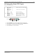
PD-1021 TMCL Firmware V1.19 Manual (Rev. 1.01 / 2012-JUL-30) Power, communication and multi-purpose I/O 35 Please note, that the module has four I/O pins including four input pins: 1 Pin Pin Pin Pin 5: 6: 7: 8: IN_O (digital) IN_1 (digital) IN_2 (digital) IN_3 (digital or analog) Please refer to the Hardware Manual for further information. Figure 3.2: I/O connector of PD-1021 3.5.15.1 I/O bank 0 – digital inputs: IN_3 can be read as digital or analogue input.
PD-1021 TMCL Firmware V1.19 Manual (Rev. 1.01 / 2012-JUL-30) 36 3.5.16 CALC (calculate) A value in the accumulator variable, previously read by a function such as GAP (get axis parameter) can be modified with this instruction. Nine different arithmetic functions can be chosen and one constant operand value must be specified. The result is written back to the accumulator, for further processing like comparisons or data transfer.
PD-1021 TMCL Firmware V1.19 Manual (Rev. 1.01 / 2012-JUL-30) 37 3.5.17 COMP (compare) The specified number is compared to the value in the accumulator register. The result of the comparison can for example be used by the conditional jump (JC) instruction. This command is intended for use in standalone operation only. The host address and the reply are only used to take the instruction to the TMCL program memory while the program loads down. It does not make sense to use this command in direct mode.
PD-1021 TMCL Firmware V1.19 Manual (Rev. 1.01 / 2012-JUL-30) 38 3.5.18 JC (jump conditional) The JC instruction enables a conditional jump to a fixed address in the TMCL program memory, if the specified condition is met. The conditions refer to the result of a preceding comparison. Please refer to COMP instruction for examples. This function is for standalone operation only. The host address and the reply are only used to take the instruction to the TMCL program memory while the program loads down.
PD-1021 TMCL Firmware V1.19 Manual (Rev. 1.01 / 2012-JUL-30) 39 3.5.19 JA (jump always) Jump to a fixed address in the TMCL program memory. This command is intended for standalone operation only. The host address and the reply are only used to take the instruction to the TMCL program memory while the program loads down. This command cannot be used in direct mode. Internal function: the TMCL program counter is set to the passed value.
PD-1021 TMCL Firmware V1.19 Manual (Rev. 1.01 / 2012-JUL-30) 40 3.5.20 CSUB (call subroutine) This function calls a subroutine in the TMCL program memory. It is intended for standalone operation only. The host address and the reply are only used to take the instruction to the TMCL program memory while the program loads down. This command cannot be used in direct mode. Internal function: the actual TMCL program counter value is saved to an internal stack, afterwards overwritten with the passed value.
PD-1021 TMCL Firmware V1.19 Manual (Rev. 1.01 / 2012-JUL-30) 41 3.5.21 RSUB (return from subroutine) Return from a subroutine to the command after the CSUB command. This command is intended for use in standalone mode only. The host address and the reply are only used to take the instruction to the TMCL program memory while the program loads down. This command cannot be used in direct mode. Internal function: the TMCL program counter is set to the last value of the stack.
PD-1021 TMCL Firmware V1.19 Manual (Rev. 1.01 / 2012-JUL-30) 42 3.5.22 WAIT (wait for an event to occur) This instruction interrupts the execution of the TMCL program until the specified condition is met. This command is intended for standalone operation only. The host address and the reply are only used to take the instruction to the TMCL program memory while the program loads down. This command cannot be used in direct mode.
PD-1021 TMCL Firmware V1.19 Manual (Rev. 1.01 / 2012-JUL-30) 43 3.5.23 STOP (stop TMCL program execution) This function stops executing a TMCL program. The host address and the reply are only used to transfer the instruction to the TMCL program memory. This command should be placed at the end of every standalone TMCL program. It is not to be used in direct mode. Internal function: TMCL instruction fetching is stopped. Related commands: none Mnemonic: STOP Binary representation: INSTRUCTION NO.
PD-1021 TMCL Firmware V1.19 Manual (Rev. 1.01 / 2012-JUL-30) 44 3.5.24 SCO (set coordinate) Up to 20 position values (coordinates) can be stored for every axis for use with the MVP COORD command. This command sets a coordinate to a specified value. Depending on the global parameter 84, the coordinates are only stored in RAM or also stored in the EEPROM and copied back on startup (with the default setting the coordinates are stored in RAM only).
PD-1021 TMCL Firmware V1.19 Manual (Rev. 1.01 / 2012-JUL-30) 45 3.5.25 GCO (get coordinate) This command makes possible to read out a previously stored coordinate. In standalone mode the requested value is copied to the accumulator register for further processing purposes such as conditioned jumps. In direct mode, the value is only output in the value field of the reply, without affecting the accumulator.
PD-1021 TMCL Firmware V1.19 Manual (Rev. 1.01 / 2012-JUL-30) 46 3.5.26 CCO (capture coordinate) The actual position of the axis is copied to the selected coordinate variable. Depending on the global parameter 84, the coordinates are only stored in RAM or also stored in the EEPROM and copied back on startup (with the default setting the coordinates are stored in RAM only). Please see the SCO and GCO commands on how to copy coordinates between RAM and EEPROM.
PD-1021 TMCL Firmware V1.19 Manual (Rev. 1.01 / 2012-JUL-30) 47 3.5.27 ACO (accu to coordinate) With the ACO command the actual value of the accumulator is copied to a selected coordinate of the motor. Depending on the global parameter 84, the coordinates are only stored in RAM or also stored in the EEPROM and copied back on startup (with the default setting the coordinates are stored in RAM only). Please note also that the coordinate number 0 is always stored in RAM only.
PD-1021 TMCL Firmware V1.19 Manual (Rev. 1.01 / 2012-JUL-30) 48 3.5.28 CALCX (calculate using the X register) This instruction is very similar to CALC, but the second operand comes from the X register. The X register can be loaded with the LOAD or the SWAP type of this instruction. The result is written back to the accumulator for further processing like comparisons or data transfer.
PD-1021 TMCL Firmware V1.19 Manual (Rev. 1.01 / 2012-JUL-30) 49 3.5.29 AAP (accumulator to axis parameter) The content of the accumulator register is transferred to the specified axis parameter. For practical usage, the accumulator has to be loaded e.g. by a preceding GAP instruction. The accumulator may have been modified by the CALC or CALCX (calculate) instruction. Related commands: AGP, SAP, GAP, SGP, GGP, GIO, GCO, CALC, CALCX Mnemonic: AAP , 0 Binary representation: INSTRUCTION NO.
PD-1021 TMCL Firmware V1.19 Manual (Rev. 1.01 / 2012-JUL-30) 50 3.5.30 AGP (accumulator to global parameter) The content of the accumulator register is transferred to the specified global parameter. For practical usage, the accumulator has to be loaded e.g. by a preceding GGP instruction. The accumulator may have been modified by the CALC or CALCX (calculate) instruction. Note: The global parameters in bank 0 are EEPROM-only and thus should not be modified automatically by a standalone application.
PD-1021 TMCL Firmware V1.19 Manual (Rev. 1.01 / 2012-JUL-30) 51 3.5.31 CLE (clear error flags) This command clears the internal error flags. It is intended for use in standalone mode only and must not be used in direct mode. The following error flags can be cleared by this command (determined by the parameter): - ALL: clear all error flags. - ETO: clear the timeout flag.
PD-1021 TMCL Firmware V1.19 Manual (Rev. 1.01 / 2012-JUL-30) 52 3.5.32 VECT (set interrupt vector) The VECT command defines an interrupt vector. It needs an interrupt number and a label as parameter (like in JA, JC and CSUB commands). This label must be the entry point of the interrupt handling routine. Related commands: EI, DI, RETI Mnemonic: VECT ,
PD-1021 TMCL Firmware V1.19 Manual (Rev. 1.01 / 2012-JUL-30) 53 3.5.33 EI (enable interrupt) The EI command enables an individual interrupt and activates interrupts in general (global interrupt enable). Please make sure to always issue a global interrupt enable in order to actually activate the interrupts individually enabled. Related command: DI, VECT, RETI Mnemonic: EI Binary representation: INSTRUCTION NO.
PD-1021 TMCL Firmware V1.19 Manual (Rev. 1.01 / 2012-JUL-30) 54 3.5.34 DI (disable interrupt) The DI command disables an individual interrupt or using parameter 255 will de-activate any interrupt. Related command: EI, VECT, RETI Mnemonic: DI Binary representation: INSTRUCTION NO.
PD-1021 TMCL Firmware V1.19 Manual (Rev. 1.01 / 2012-JUL-30) 55 3.5.35 RETI (return from interrupt) This command terminates the interrupt handling routine, and the normal program execution continues. At the end of an interrupt handling routine the RETI command must be executed. Internal function: the saved registers (A register, X register, flags) are copied back. Normal program execution continues. Related commands: EI, DI, VECT Mnemonic: RETI Binary representation: INSTRUCTION NO.
PD-1021 TMCL Firmware V1.19 Manual (Rev. 1.01 / 2012-JUL-30) 56 3.5.36 Customer Specific TMCL Command Extension (UF0… UF7/user function) The user definable functions UF0… UF7 are predefined functions for user specific purposes. Contact TRINAMIC for the customer specific programming of these functions. Internal function: call user specific functions implemented in C by TRINAMIC. Related commands: none Mnemonic: UF0… UF7 Binary representation: INSTRUCTION NO.
PD-1021 TMCL Firmware V1.19 Manual (Rev. 1.01 / 2012-JUL-30) 57 3.5.38 TMCL Control Functions The following functions are for host control purposes only and are not allowed for standalone mode. In most cases, there is no need for the customer to use one of those functions (except command 139). TMCL control commands have no mnemonics, as they cannot be used in TMCL programs. These Functions are to be used only by the TMCL-IDE (e.g. to download a TMCL application into the module).
PD-1021 TMCL Firmware V1.19 Manual (Rev. 1.01 / 2012-JUL-30) SPECIAL REPLY FORMAT OF COMMAND 136: Type set to 0 - reply as a string: Byte index 1 2… 9 Contents Host Address Version string (8 characters, e.g. 1021V117) There is no checksum in this reply format! Type set to 1 - version number in binary format: - Please use the normal reply format. The version number is output in the value field of the reply in the following way: Byte index in value field 1 2 3 4 www.trinamic.
PD-1021 TMCL Firmware V1.19 Manual (Rev. 1.01 / 2012-JUL-30) 59 4 Axis Parameters The following sections describe all axis parameters that can be used with the SAP, GAP, AAP, STAP and RSAP commands. MEANING OF THE LETTERS IN COLUMN ACCESS: Access type R W E Related command(s) GAP SAP, AAP STAP, RSAP Description Parameter readable Parameter writable Parameter automatically restored from EEPROM after reset or power-on.
PD-1021 TMCL Firmware V1.19 Manual (Rev. 1.01 / 2012-JUL-30) Number 8 Axis Parameter Position reached 9 Home switch status Right limit switch status Left limit switch status Right limit switch disable Left limit switch disable 10 11 12 13 128 Ramp mode 130 Minimum speed 140 Microstep resolution 161 Double step enable 162 Chopper blank time 163 Chopper mode 164 Chopper hysteresis decrement www.trinamic.
PD-1021 TMCL Firmware V1.19 Manual (Rev. 1.01 / 2012-JUL-30) Number 165 166 167 168 169 Axis Parameter Chopper hysteresis end Description Hysteresis end setting. Sets the hysteresis end value after a number of decrements. Decrement interval time is controlled by axis parameter 164. -3… -1 negative hysteresis end setting 0 zero hysteresis end setting 1… 12 positive hysteresis end setting Chopper Hysteresis start setting.
PD-1021 TMCL Firmware V1.19 Manual (Rev. 1.01 / 2012-JUL-30) Number 173 Axis Parameter stallGuard2™ filter enable 174 stallGuard2™ threshold 175 Slope control high side 176 Slope control low side short protection disable 177 178 Short detection timer 180 smartEnergy actual current Description Enables the stallGuard2 filter for more precision of the measurement. If set, reduces the measurement frequency to one measurement per four fullsteps.
PD-1021 TMCL Firmware V1.19 Manual (Rev. 1.01 / 2012-JUL-30) Number 193 Axis Parameter Description Ref.
PD-1021 TMCL Firmware V1.19 Manual (Rev. 1.01 / 2012-JUL-30) Number 209 210 212 214 215 254 Axis Parameter Description Encoder position The value of an encoder register can be read out or written. Encoder Prescaler for the encoder. prescaler Maximum When the actual position (parameter 1) and the encoder encoder position (parameter 209) differ more deviation than set here the motor will be stopped. This function is switched off when the maximum deviation is set to zero.
PD-1021 TMCL Firmware V1.19 Manual (Rev. 1.01 / 2012-JUL-30) 65 4.2 stallGuard2 The module is equipped with TMC262 motor driver chip. The TMC262 features load measurement that can be used for stall detection. stallGuard2 delivers a sensorless load measurement of the motor as well as a stall detection signal. The measured value changes linear with the load on the motor in a wide range of load, velocity and current settings. At maximum motor load the stallGuard2 value goes to zero.
PD-1021 TMCL Firmware V1.19 Manual (Rev. 1.01 / 2012-JUL-30) COOLSTEP RELATED 66 AXIS PARAMETERS Note: smartEnergy is an earlier name for coolStep. Number I6 I7 I168 I169 I171 I183 Axis parameter Description The maximum value is 255. This value means 100% of the maximum current of the module. The current adjustment is within the range 0… 255 and can be adjusted in 32 steps (0… absolute max. current (CS / 255 divided by eight; e.g. step 0 = 0… 7, step 1 = 8… 15 and so Current Scale) on).
PD-1021 TMCL Firmware V1.19 Manual (Rev. 1.01 / 2012-JUL-30) 67 5 Global parameters GLOBAL PARAMETERS ARE GROUPED INTO 4 BANKS: bank bank bank bank - 0 1 2 3 (global configuration of the module) (user C variables) (user TMCL variables) (interrupt configuration) Please use SGP and GGP commands to write and read global parameters. 5.1 Bank 0 Parameters with numbers from 64 on configure parameters like the serial address of the module RS485 baud rate.
PD-1021 TMCL Firmware V1.19 Manual (Rev. 1.01 / 2012-JUL-30) Number 73 75 76 77 79 81 84 128 129 130 132 133 Global parameter Configuration EEPROM lock flag Telegram pause time Description Write: 1234 to lock the EEPROM, 4321 to unlock it. Read: 1=EEPROM locked, 0=EEPROM unlocked. Pause time before the reply is sent. For RS485 it is often necessary to set it to 15 (for RS485 adapters controlled by the RTS pin).
PD-1021 TMCL Firmware V1.19 Manual (Rev. 1.01 / 2012-JUL-30) 69 5.3 Bank 2 Bank 2 contains general purpose 32 bit variables for the use in TMCL applications. They are located in RAM and the first 56 variables can be stored permanently in EEPROM, also. After booting, their values are automatically restored to the RAM. Up to 256 user variables are available.
PD-1021 TMCL Firmware V1.19 Manual (Rev. 1.01 / 2012-JUL-30) 70 5.4 Bank 3 Bank 3 contains interrupt parameters. Some interrupts need configuration (e.g. the timer interval of a timer interrupt). This can be done using the SGP commands with parameter bank 3 (SGP , 3, ). The parameter number defines the priority of an interrupt. Interrupts with a lower number have a higher priority.
PD-1021 TMCL Firmware V1.19 Manual (Rev. 1.01 / 2012-JUL-30) 71 6 Hints and Tips This chapter gives some hints and tips on using the functionality of TMCL™, for example how to use and parameterize the built-in reference point search algorithm or the incremental sensOstep™ encoder. Further you will find basic information about stallGuard2™ and coolStep™. 6.1 Reference Search The built-in reference search features switching point calibration and support of one or two reference switches.
PD-1021 TMCL Firmware V1.19 Manual (Rev. 1.01 / 2012-JUL-30) SAP 193, 0, 1 negative limit switch Search left stop switch only. SAP 193, 0, 2 negative limit switch positive limit switch Search right stop switch, then search left stop switch. SAP 193, 0, 3 negative limit switch positive limit switch Search right stop switch, then search left stop switch from both sides. SAP 193, 0, 4 negative limit switch Search left stop switch from both sides. www.trinamic.
PD-1021 TMCL Firmware V1.19 Manual (Rev. 1.01 / 2012-JUL-30) SAP 193, 0, 5 negative limit switch positive limit switch home switch Search home switch in negative direction, reverse the direction when left stop switch reached. SAP 193, 0, 6 negative limit switch positive limit switch home switch Search home switch in positive direction, reverse the direction when right stop switch reached. SAP 193, 0, 7 home switch Search home switch in positive direction, ignore end switches.
PD-1021 TMCL Firmware V1.19 Manual (Rev. 1.01 / 2012-JUL-30) 74 6.2 Changing the Prescaler Value of an Encoder The built-in encoder has 1024 steps per rotation. FOR THE OPERATION WITH ENCODER PLEASE CONSIDER THE FOLLOWING HINTS: - The encoder counter can be read by software and can be used to control the exact position of the motor. This also makes closed loop operation possible. To read out or to change the position value of the encoder, axis parameter #209 is used.
PD-1021 TMCL Firmware V1.19 Manual (Rev. 1.01 / 2012-JUL-30) 75 6.3 Using the RS485 Interface With most RS485 converters that can be attached to the COM port of a PC the data direction is controlled by the RTS pin of the COM port. Please note that this will only work with Windows 2000, Windows XP or Windows NT4, not with Windows 95, Windows 98 or Windows ME (due to a bug in these operating systems). Another problem is that Windows 2000/XP/NT4 switches the direction back to receive too late.
PD-1021 TMCL Firmware V1.19 Manual (Rev. 1.01 / 2012-JUL-30) 76 7 TMCL Programming Techniques and Structure 7.1 Initialization The first task in a TMCL program (like in other programs also) is to initialize all parameters where different values than the default values are necessary. For this purpose, SAP and SGP commands are used. 7.2 Main Loop Embedded systems normally use a main loop that runs infinitely. This is also the case in a TMCL application that is running stand alone.
PD-1021 TMCL Firmware V1.19 Manual (Rev. 1.01 / 2012-JUL-30) 77 Just have a look at the file TMCLParam.tmc provided with the TMCL-IDE. It contains symbolic constants that define all important parameter numbers. Using constants for other values makes it easier to change them when they are used more than once in a program. You can change the definition of the constant and do not have to change all occurrences of it in your program. 7.
PD-1021 TMCL Firmware V1.19 Manual (Rev. 1.01 / 2012-JUL-30) 78 7.6 Mixing Direct Mode and Standalone Mode Direct mode and standalone mode can also standalone mode, direct mode commands are program running in standalone mode). So, it motor in direct mode while a TMCL program is be mixed. When a TMCL program is being executed in also processed (and they do not disturb the flow of the is also possible to query e.g. the actual position of the running.
PD-1021 TMCL Firmware V1.19 Manual (Rev. 1.01 / 2012-JUL-30) 8 Life Support Policy TRINAMIC Motion Control GmbH & Co. KG does not authorize or warrant any of its products for use in life support systems, without the specific written consent of TRINAMIC Motion Control GmbH & Co. KG. Life support systems are equipment intended to support or sustain life, and whose failure to perform, when properly used in accordance with instructions provided, can be reasonably expected to result in personal injury or death.
PD-1021 TMCL Firmware V1.19 Manual (Rev. 1.01 / 2012-JUL-30) 9 Revision History 9.1 Document Revision Version Date 1.00 1.01 2012-JUN-12 2012-JUL-30 Author SD – Sonja Dwersteg GE – Göran Eggers SD SD Description First complete version. Global parameter 79 added Figure 8.1: Document revision 9.2 Firmware Revision Version 1.09 1.10 1.15 1.17 1.