
User manual

PD-1021 TMCL Firmware V1.19 Manual (Rev. 1.01 / 2012-JUL-30) 6
www.trinamic.com
2 Putting the PANdrive into Operation
Here you can find basic information for putting your PD-1021 into operation. If you are already common
with TRINAMICs modules you may skip this chapter.
The things you need:
- PD-1021
- RS485 interface converter with cables
- Nominal supply voltage +24V DC for your PANdrive
- TMCL-IDE program and PC
2.1 Basic Set-Up
The following paragraph will guide you through the steps of connecting the unit and making first
movements with the motor.
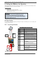
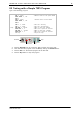
2.1.1 Connecting the Module
PRECAUTIONS
Do not connect or disconnect the PD-1021 while powered!
Do not connect or disconnect the motor while powered!
Do not exceed the maximum power supply voltage of 28V DC!
Note, that the module is not protected against reverse polarity!
START WITH POWER SUPPLY OFF!
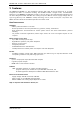
Motor
Pin 1 B2
Pin 2 B1
Pin 3 A2
Pin 4 A1
Converter
e.g. USB-2-485
1
1
RS485
Pin 1 GND
Pin 3 RS485+
Pin 4 RS485-
Note, that the
GND pin has to be
used for the
power supply and
for the RS485
interface.
Power Supply
Pin 1 GND
Pin 2 9… 28V DC
Figure 2.1: Starting up
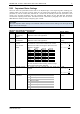
2. Connect RS485 interface and power supply
Pin
Label
Description
1
GND
GND
2
VDD
VDD (+9V…+28V)
3
RS485+
RS485 interface, diff. signal (non-
inverting)
4
RS485-
RS485 interface, diff. signal (inverting)
5
IN_0
Digital input (+24V compatible)
Alternate function 1: step input
Alternate function 2: left stop switch
6
IN_1
Digital input (+24V compatible)
Alternate function 1: direction input
Alternate function 2: right stop switch
7
OUT_0 / IN_2
Open drain output with freewheeling
diode
(max. 100mA)
Alternate function 1:
digital input (+24V compatible)
Alternate function 2:home switch
8
OUT_1 / IN_3
Open drain output with freewheeling
diode (max. 100mA)
Alternate function 1: digital input
(+24V compatible)
Alternate function 2: analog input