PANDrive PD-110-42 and TMCM-110-42 42mm / NEMA-17 Stepper Motor Mechatronic Module TMCM-110-42 Electronics Manual Version: 1.13 December 23th, 2005 Sternstraße 67 D - 20357 Hamburg, Germany Phone +49-40-51 48 06 - 0 FAX: +49-40-51 48 06 - 60 http://www.trinamic.
TMCM-110-42 Manual Contents 1 2 3 Features ........................................................................................................................................... 3 Life support policy............................................................................................................................. 4 Electrical and Mechanical Interfacing............................................................................................... 5 3.1 Dimensions.............................
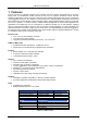
TMCM-110-42 Manual 1 Features The PD-110-42 is an intelligent stepper motor controller and driver module mounted directly on a 42mm flange motor. The TMCM-110 module converts the motor into a compact mechatronic device with bus oriented or stand-alone control. The motor, switches, power and the multi purpose I/Os can be connected via small pluggable connectors. The TMCM-110 comes with the PC based software development environment TMCL-IDE for the Trinamic Motion Control Language (TMCL).
TMCM-110-42 Manual 2 Life support policy TRINAMIC Motion Control GmbH & Co. KG does not authorize or warrant any of its products for use in life support systems, without the specific written consent of TRINAMIC Motion Control GmbH & Co. KG. Life support systems are equipment intended to support or sustain life, and whose failure to perform, when properly used in accordance with instructions provided, can be reasonably expected to result in personal injury or death. © TRINAMIC Motion Control GmbH & Co.
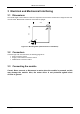
TMCM-110-42 Manual 5 3 Electrical and Mechanical Interfacing 3.1 Dimensions The overall height of the module is 17mm.The components on back of the module have a height of 5mm and on front 10mm. Beware that connectors on the front are upright. 41,8 5,4 5,4 41,8 M3 M3 5,4 5,4 Figure 3.1: Mounting holes (all dimensions in millimeters) 3.
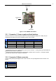
TMCM-110-42 Manual 6 Connector 2 Pin 1 Connector 3 Pin 1 Pin 1 Connector 1 Figure 3.2: The TMCM-110-42 module 3.3.1 Connector 1: Power supply and host interface Use this connector to connect the power and the host interface (RS232, RS485, IIC or CAN). The pin assignments are different for the four available versions of the module. Pin 1 2 3 4 5 RS232 GND +7..34V DC GND RxD TxD RS485 1) GND +7..34V DC GND RS485+ RS485 - Function IIC GND +7..34V DC GND SCL SDA CAN 2) GND +7..
TMCM-110-42 Manual 3.3.3 Connector 3: Additional I/O All other inputs and outputs of the module can be connected here. These are the limit switches, a general purpose input and a general purpose output. The limit switch inputs are equipped with internal pull-up resistors, so they have to be connected to GND via normally closed switches. The general purpose input can either be used as a digital TTL input or as an analogue input (0..5V).
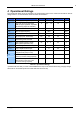
TMCM-110-42 Manual 8 4 Operational Ratings The operational ratings show the intended / the characteristic range for the values and should be used as design values. In no case shall the maximum values be exceeded. Symbol Parameter Min Typ Max Unit VS Power supply voltage for operation 7 12 ... 30 34*) V ICOIL Motor coil current for sine wave peak (chopper regulated, adjustable via software) (adjust via Software) 0 0.4 … 1.5 1.5 A IMC Continuous motor current (RMS) 0 0.3... 1.1 1.
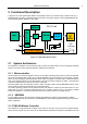
TMCM-110-42 Manual 9 5 Functional Description In Figure 5.1 the main parts oft the TMCM-110 module are shown. The module mainly consists of the µC, a TMC428 motion controller, a TMC246 stepper motor driver, the TMCL program memory (EEPROM) and the host interfaces (RS232, RS485, IIC and CAN). TMCL EEPROM Host RS-232 or RS-485 or IIC or CAN I/O 7..30V DC µC PD-110-42 TMC428 Step Driver TMC246 2 Motor +5V REFSwitches 5V Power Supply Figure 5.1: Application Environment 5.
TMCM-110-42 Manual to the TMC428 via SPI by the microcontroller. Calculation of ramps and speed profiles are done internally by hardware based on the target motion parameters. 5.1.4 TMC246 Motor Driver The stepper motor driver used on the TMCM-110 module is the TMC246 chip. This driver is very dependable, because it provides a variety of protection and diagnostic features, which even can be read out by the user software. Its 16x up to 32x microstepping gives a quiet and precise motor operation.
TMCM-110-42 Manual 11 5.5 StallGuard™ - Sensorless Motor Stall Detection The integrated StallGuard™ feature gives a simple means to detect mechanical blocking of the motor. This can be used for precise absolute referencing, when no reference switch is available. The load value can be read using a TMCL command or the module can be programmed so that the motor will be stopped automatically when it has been obstructed or the load has been too high.
TMCM-110-42 Manual 6 Putting the TMCM-110 into Operation On the basis of a small example it is shown step by step how the TMCM-110-42 is set into operation. Users who are already familiar with TMCL and other Trinamic modules may skip this chapter. Example: The following application is to be implemented on the TMCM-110-42 module using the TMCL-IDE Software development environment. A formula how “speed” is converted into a physical unit like rotations per seconds can be found in chapter 7.1.
TMCM-110-42 Manual 13 7 TMCM-110 Operational Description 7.1 Calculation: Velocity and Acceleration vs. Microstep- and Fullstep Frequency The values of the parameters sent to the TMC428 do not have typical motor values, like rotations per second as velocity. But these values can be calculated from the TMC428 parameters, as shown in this document.
TMCM-110-42 Manual Example: f_CLK = 16 MHz on the TMCM-110 module velocity = 1000 a_max = 1000 pulse_div = 1 ramp_div = 1 usrs = 6 msf = 16 MHz ⋅1000 =122070.3125 Hz 21 ⋅ 2048 ⋅ 32 fsf [ Hz ] = a= 122070.3125 = 1907.35Hz 26 (16 Mhz ) 2 ⋅1000 MHz =119.208 1+1+ 29 s 2 af = MHz s = 1,863 MHz 6 s 2 119.208 If the stepper motor has e.g. 72 fullsteps per rotation, the number of rotations of the motor is: 1907.35 fsf = = 26.49 72 fullsteps per rotation 1907.35 ⋅ 60 fsf ⋅ 60 RPM = = = 1589.
TMCM-110-42 Manual 8 Software TMCL, the Trinamic Motion Control Language is used to send commands from the host to the TMCM-110 module and to write programs that can be stored in the EEPROM of the module so that the module can execute the TMCL commands in a stand-alone mode. TMCL is described in a separate documentation, the TMCL Reference and Programming Manual.
TMCM-110-42 Manual 9 Revision History 9.1 Documentation Revision Version 1.00 1.03 1.10 1.11 1.12 1.13 Comment Initial Release 16-Jul-04 27-Jul-04 1-Oct-04 4-Oct-04 23-Dec-05 Author OK OK OK OK TG BD, HC Description Initial version CAN interface added Major revision Minor error corrections Corrected mounting dimensions Added Pan-Drive documentation and major revision Table 9.1: Documentation Revisions 9.2 Firmware Revision Version 3.
TMCM-110-42 Manual 10 References [TMCL] TMCL manual (see http://www.trinamic.com) Copyright © 2005, TRINAMIC Motion Control GmbH & Co.